Content of this Document
This document provides a detailed description of the Slicer and associated parameters.
If you want to have a more in depth of slicing parameters, you are at the right place.
Introduction
The Slicer is a detailed view of the ChopChop3D Slicer.
If you need to setup different slicing profiles on different layer ranges with different layer heights, then you are at the right place.
Slicer overview
Requirement You need to have at least one STL model inside an existing or new Project.
Go in the Main menu and click on "Slicer/Slice".
The Slicer panel is decomposed as follow:
- Profile: this is used to load/unload profiles.
- Models: this is used to set configurations to models.
- Layers: that contains all layers ranges with associated slicing profiles.
- Current Range: the current layer range under edition.
- Insets: that contains all parameters associated to Insets.
- Infills: that contains all parameters associated to Infills.
- Top: that contains all parameters associated to Top.
- Bottom: that contains all parameters associated to Bottom.
- Temperatures: that contains all parameters associated to Temperatures.
- Adhesion: that contains specific parameters for Skirt, Raft and Brim settings to improve adhesion of parts to the bed.
- Support: that contains all settings to handle Support structures.
- Cooling: that contains all settings for the Cooling.
- GCode: that contains settings related to the printer for the GCode generation.
- Scheduling: that contains settings related to the order of each kind of toolpath performed for each slice.
- Travel: that contains settings related to travel computation of each kind of toolpath.
- Polygons: that contains settings related to polygons.
Profile
This is the entry tab that allows to select the Printer, the Bundle and the Profile to be used for the Slicer.
Important: there is not any kind of autosaving of the modified profile, if you performed any modification on a profile, you will have to save it explicitly.
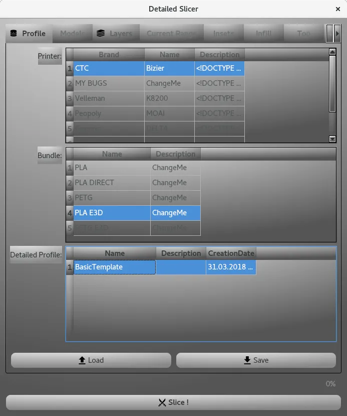
- Load Just select the Printer, the Bundle and the Profile, then click on Load button. You will be asked for confirmation.
- Save Similarly to Load, select the Printer, the Bundle, then click on Save button. You will be asked the name of the profile to save.
- Use Default Extruder propagates the Default Extruder to all printing phases of the selected ranges.
- Edit Default Extruder opens the dialog to edit the Default Extruder, you can see the details by following this link.
- Load Quick Slice Profile opens a Quick Slice Dialog, allowing to reuse an existing Quick Slice Profile for the selected range.
- Layer Height sets the layer height
- From and To that specifies the bound of the interval.
- Layers the amount of layers.
- Name an optional name.
- Split allows to refine a range as a new list of ranges.
- Join joins two or more ranges together.
- Edit loads the associated slicer configuration for edition.
- Load Quick Slice Profile opens a Quick Slice Dialog, allowing to reuse an existing Quick Slice Profile for the selected range.
- Check Intervals checks for instance that all intervals are contiguous.
- Show Intervals shows in the Viewer planes associated to each interval.
- Hide Intervals hides in the Viewer planes associated to each interval.
- Insert that inserts a new range for edition.
- Delete that delete a given range.
- Check Intervals checks for instance that all intervals are contiguous.
- Show Intervals shows in the Viewer planes associated to each interval.
- Hide Intervals hides in the Viewer planes associated to each interval.
- Set Current Layer Range : that propagates the edited parameters to the edited layer range.
- Set All Layer Ranges : that propagates to ALL layer ranges the given configuration. This helps saving time on the edition.
- Use Default Extruder : that propagates the Default Extruder to all printing phases under edition.
- Insets Count which is the number of insets you want.
- XY Shell Thickness the resulting thickness obtained from extruders' insets configuration.
- Cleanup Maximum Length which contains the maximum length of insets to filter out (typically non printable features).
- Cleanup Maximum Area which contains the maximum area of insets to filter out (typically non printable features).
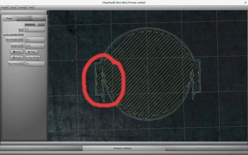
- Offset Mitter Limit is setting the ratio of the point length to the extrusion width before the mitered join becomes a beveled square joint. The value of 10 is giving sharp details.
Small example, the miter limit is set to 10.
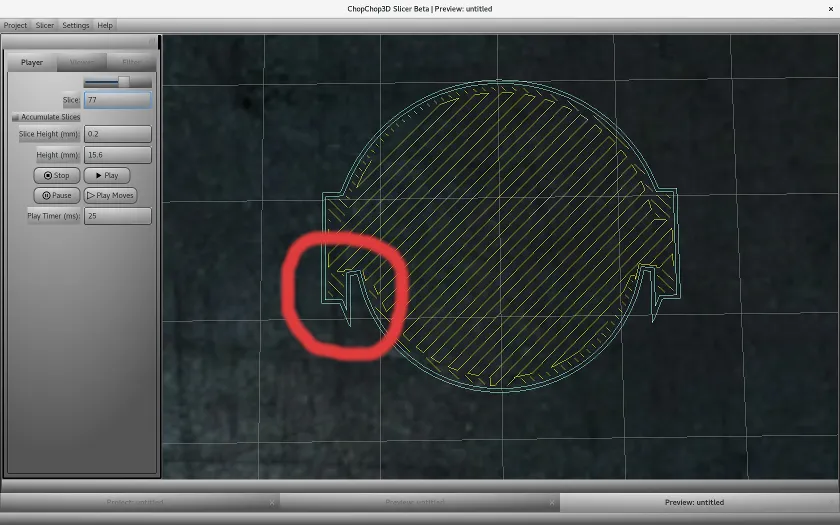
While here, the miter limit is set to 5.
- Extrusion Widths is the list of extrusion widths used for each inset. You can Insert or Delete through a right-click in the given list.
You can configure for each of them its own Extruder through the button Extruder Configuration that will popup the associated Extruder dialog for it. You can have further details on the Extruder by following this link.
If needed you can propagate the Default Extruder for selected entries with the button Use Default Extruder, or propagate on all Insets with the button Use Default Extruder for All. - Enable Extrusion Overlap enables/disables to customize extrusion overlap between Insets.
- Merge Thin Walls enables/disables the merging of Thin Walls.
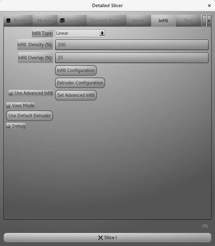
- Infill Type it is the infill applied if Use Advanced Infill is disabled. It is set through the Infill Configuration.
- Infill Density it is the percentage of the previous infill resulting from the Infill Configuration.
- Infill Overlap it is the amount of overlap with the Insets.
- Infill Configuration shows the Infill dialog to configure the given Infill. For further details, you can follow this link.
- Extruder Configuration shows the Extruder dialog associated to the given Infill. For further details, you can follow this link.
- Use Advanced Infill when enabled, the advanced top infill is used
- Set Advanced Infill opens the Advanced Infill dialog associated to the Infill print phase. You can have further details in the Infill document.
- Vase Mode enables/disables the Vase Mode.
- Use Default Extruder propagates the Default Extruder values inside the Infill Extruder.
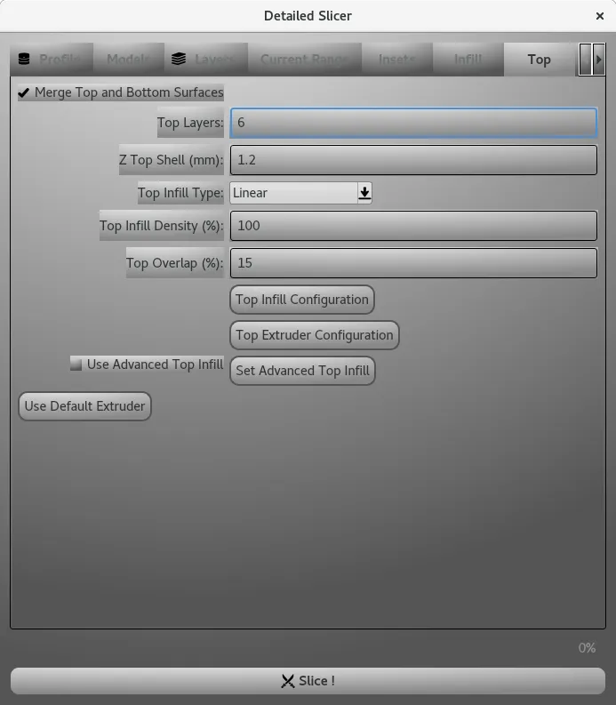
- Merge Top and Bottom uses the Top Infill and the Top Extruder, and merge the Top and Bottom printing phases when enabled.
- Top Layers is the number of layers used for the Top.
- Z Top Shell is the height in mm of the Top.
- Top Infill Type it is the infill applied if Use Advanced Infill is disabled. It is set through the Top Infill Configuration.
- Top Infill Density it is the percentage of the previous infill resulting from the Top Infill Configuration.
- Top Infill Overlap it is the amount of overlap with the Insets.
- Top Infill Configuration shows the Infill dialog to configure the given Infill. For further details, you can follow this link.
- Top Extruder Configuration shows the Extruder dialog associated to the given Infill. For further details, you can follow this link.
- Use Advanced Top Infill when enabled, the advanced top infill is used.
- Set Advanced Top Infill opens the Advanced Infill dialog associated to the Infill print phase. You can have further details in the Infill document. Use Default Extruder propagates the Default Extruder values inside the Infill Extruder.
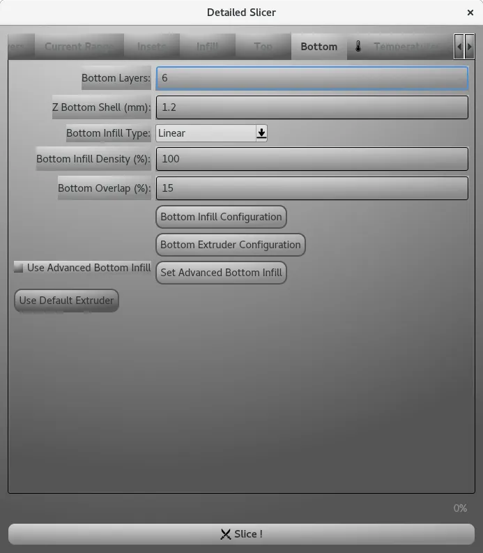
- Bottom Layers is the number of layers used for the Bottom.
- Z Bottom Shell is the height in mm of the Bottom.
- Bottom Infill Type it is the infill applied if Use Advanced Infill is disabled. It is set through the Bottom Infill Configuration.
- Bottom Infill Density it is the percentage of the previous infill resulting from the Bottom Infill Configuration.
- Bottom Infill Overlap it is the amount of overlap with the Insets.
- Bottom Infill Configuration shows the Infill dialog to configure the given Infill. For further details, you can follow this link.
- Bottom Extruder Configuration shows the Extruder dialog associated to the given Infill. For further details, you can follow this link.
- Use Advanced Bottom Infill when enabled, the advanced top infill is used
- Set Advanced Bottom Infill opens the Advanced Infill dialog associated to the Infill print phase. You can have further details in the Infill document. Use Default Extruder propagates the Default Extruder values inside the Infill Extruder.
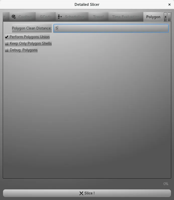
- Polygon Clean Distance: is reducing the size of polygons by applying the given distance in µm. Most probably your printer is not able to print details under 10µm, it helps to reduce the size of the polygons, speed up the slicing and reduce the size of the GCode. If you are using a high precision printer using SLA for instance, you can set this value to 0. The value of 5 is a good balance.
- Perform Polygons Unions is performing the union of overlapping polygons that can be found during the Vectorization. It should be enabled by default.
- Keep Only Polygon Shells is keeping the parent polygon inside a hierarchy of polygons. For instance, it can be used to print in Vase mode a Vase that was not design as a full solid model, or if you have an hollowed model that you want to print in solid mode.
Printer, Bundle
You can create and you can remove entries for both Printers and Bundles through the Contextual Menu that can be accessed through a Right Click in the Printer or Bundle List.
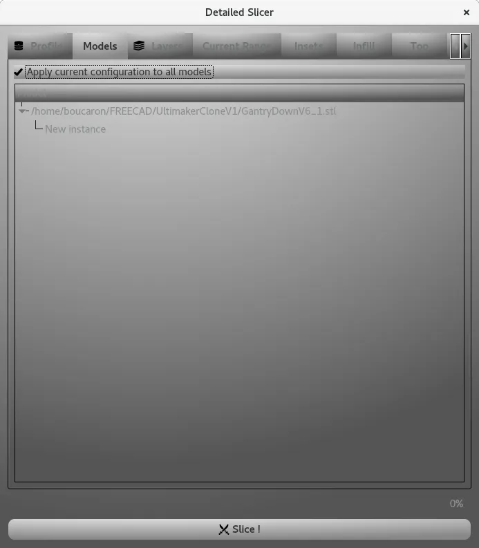
Models
Use this tab to set the same configuration to all models, or if you want to set to each model a specific configuration
Layers
This tab contains the list of ranges of layers, where each range has its specific configuration and the configuration of the Default Extruder.
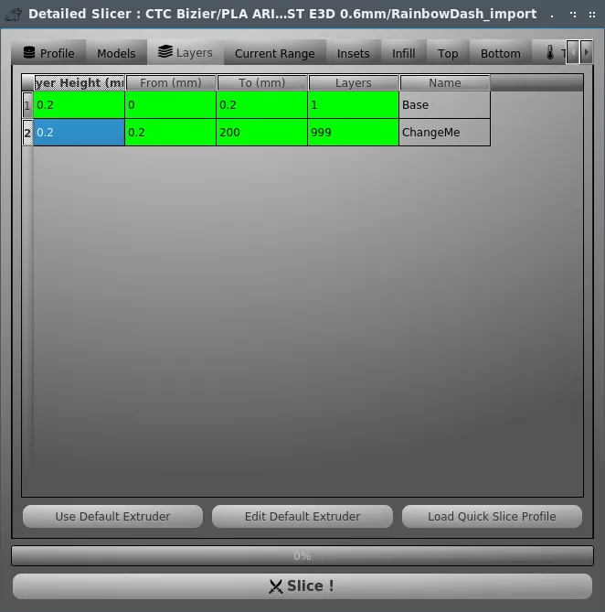
ChopChop3D Slicer enables each printing phase to have its own extruder, the Default Extruder enables to simplify the edition through reuse/propagation of this Default Extruder.
Each layer range has the following:
Load Quick Slice Profile
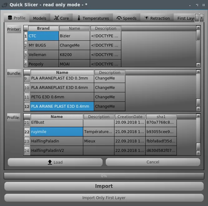
This feature enables to reuse directly a Quick Slice Profile for the given selected range.
First, you load a profile, you can also edit the values if you want to modify anything (the saved profile will not be modified).
Then, you can import it directly to the selected range, or you can only import it as a first layer (with first layer overrides).
Once it is imported, you can perform any modification you want at the given range.
Split
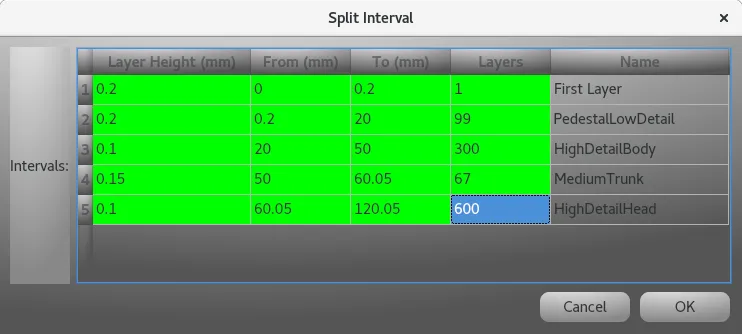
The Split is the refinement tool to improve/reduce details on ranges of layers. When a Split is performed on a given interval the following dialog will popup.
You can perform the following actions, accessed by a right-click inside the list of ranges :
Current Range

This is the Current Range under edition.
BE CAREFUL ! Once you have finished your edition of the configuration, this is the tab you have to use to propagate the changes.
It contains the following parameters borrowed from the Layers tab: Layer Height, Range Start, Range End .
There are also 3 buttons :
Insets
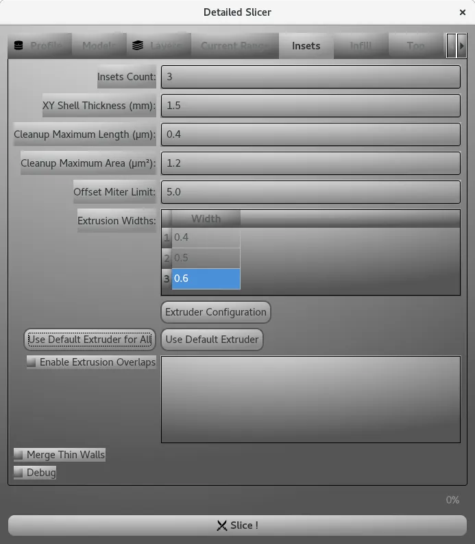
This is the tab used to set parameters for the various insets. It is decomposed as follows :
Infill
Top
Bottom
Temperatures
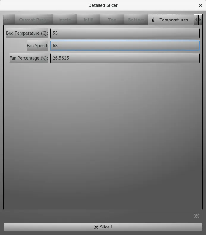
It contains the Bed Temperature and the Fan Speed either as native or percentage value.
Polygons