Content of this Document
The purpose of this document is to detail the Infill inside ChopChop3D Slicer:Introduction
The infill is a repetitive pattern used to "fill" the part.
It has different purposes for instance: the strength of the part, the aesthetic of the visible flat surfaces.
ChopChop3D Slicer implements common 2D infills with its own way:
- Any kind of infill is available and customizable in any feature that requires an infill, whether it seems logical or not to have it, you have the freedom to use it and to experiment.
- Any infill instance have its own tool and associated extruder parameters.
- We use distance based metrics.
Quick Slicer
The Quick Slicer is implementing the default policy as found in many slicers: the extruder nozzle size is used as the extrusion width, then you set the percentage of the infill from which the distance is obtained.
The Default Extruder applies by default to Top/Bottom, Infill, Raft Infill.
It is defined by the various settings found for instance in the tab for the Speeds, the Temperature, the Retraction. There is the button Use Default Extruder that can propagate its parameters across all printing phases: it saves time and it reduces the risk of mistakes when you create/edit a profile.
The Top/Bottom infills are set in the Core/Top/Bottom tab, and the Infill is set in the Core/Infill tab.
The rotation of those infills are alternated by default to -45 and 45 degrees layer by layer.
For Support Infills, we use the distance metric approach by default: you always have a pair Infill/Extruder explicitly defined. You can easily propagate the Default Extruder if needed, for any support infill there is an associated button Use Default Extruder available.
If you want to use the distance metric approach for either Top/Bottom or Infill, you can always use an Advanced Infill that can be set inside the appropriate tab. We detail this further in the Advanced Infill section.
Slicer
The Slicer is implementing the distance metric approach: it is a pair Infill/Extruder. The Infill is always defined through the same Infill dialog box that we detail just after. The Default Extruder is available at the Layers tab. When you edit a layers range, the infill parameters are available in each associated tab: Top, Bottom, Infill ...
Infill Dialog
The infill dialog contains a tab for each kind of infill, the selected tab is the infill you are using, if you want to change it you simply change the tab or you edit any shown parameter.
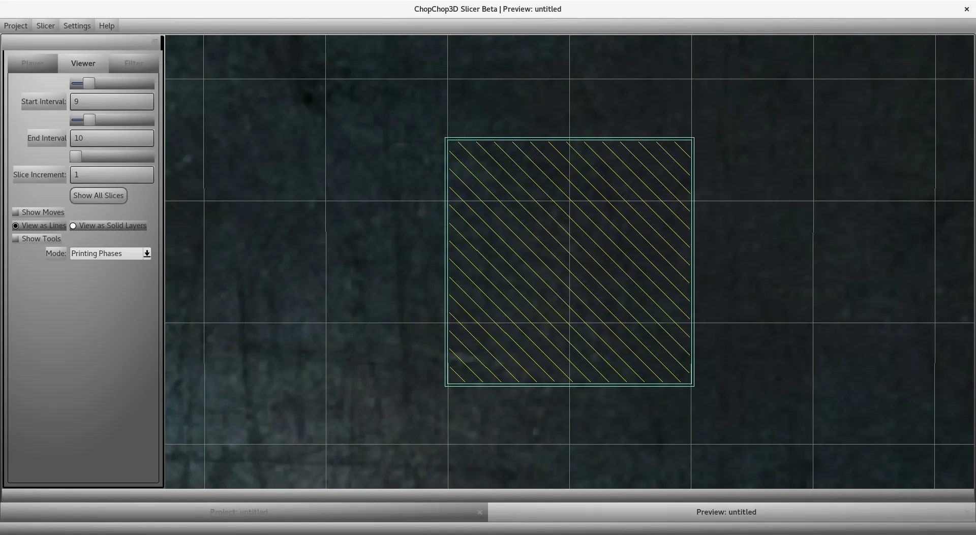
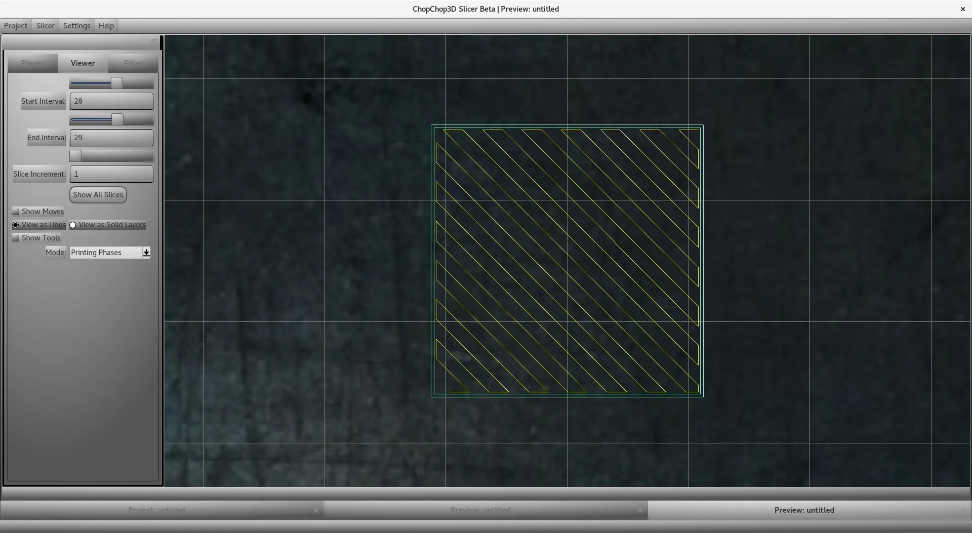
Line
The line infill is a line where both ends are attached to the shell of the part.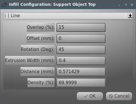
Follows the description of the parameters:
- Overlap: it is the amount of overlap of the infill with the shell.
- Offset: it is an offset that allows to shift the infill. For instance, it can be used to have a line to match a specific corner of a part.
- Rotation: it is the rotation in degrees of the line.
- Extrusion Width: it is the extrusion width used, that can be different from the nozzle diameter.
- Distance: it is the distance in between lines.
- Density: it is the density in percents of the infill, you can use either the Distance or the Density.
ZigZag
The ZigZag infill is a line infill where alternatively ends of successive lines are following the perimeter of the part.Parameters are detailed in the Line infill.
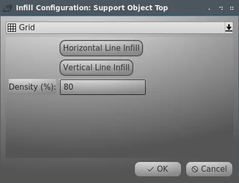
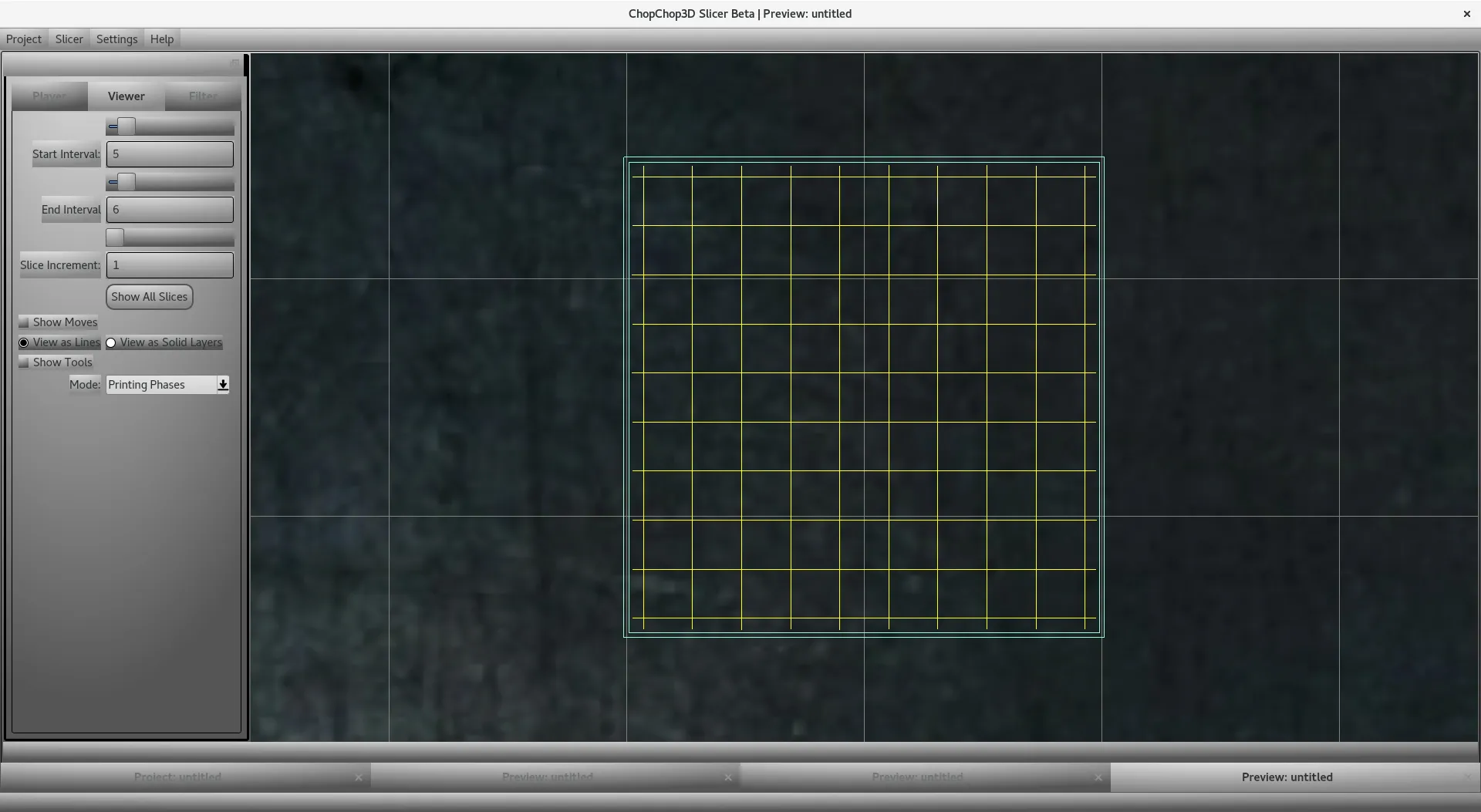
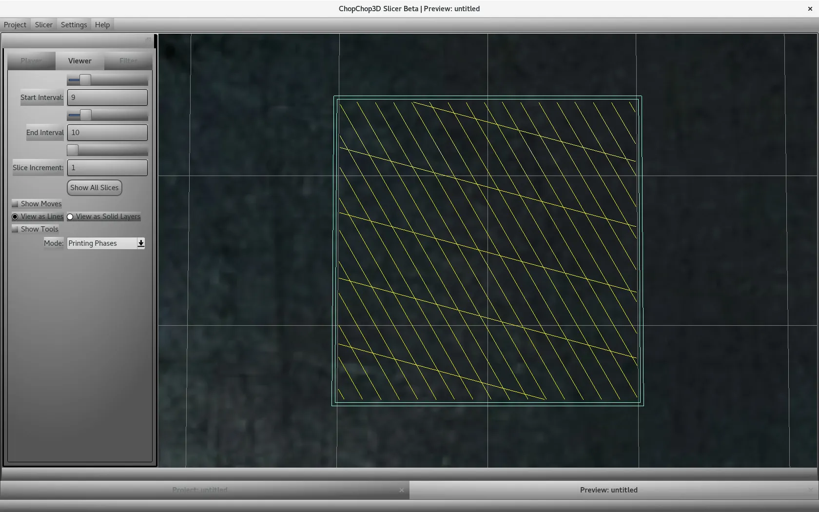
Grid
The grid infill is just the composition of 2 line infills. The core idea is that you have the freedom to define it as you want.You can set for each line its own set of parameters through the use of each button that will pop-up the set of parameters for the given line, for the moment we assume that there is the same extruder for both.The density is just the combination of densities of each line.
Parameters for each line are detailed in the Line infill.
The default grid infill found in the Quick Slicer.
An example of custom grid infill with a dense one and a sparse crossing one.
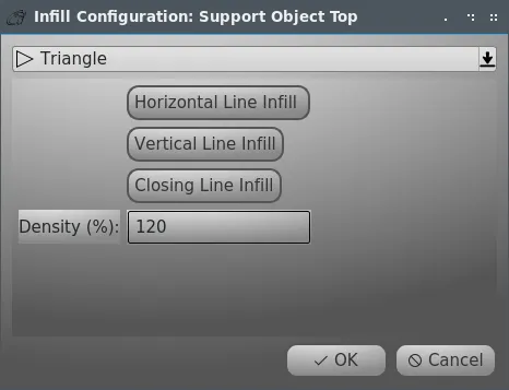
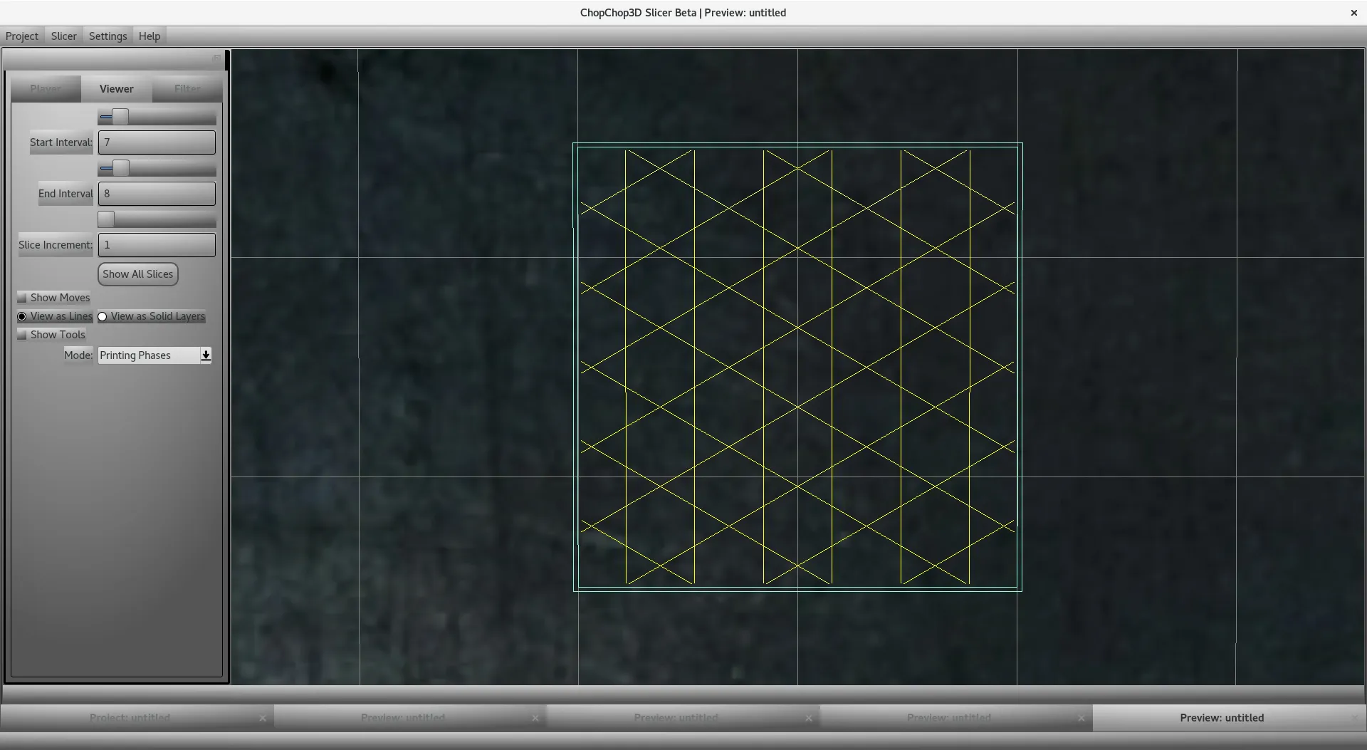
Triangle
The triangle infill is the composition of 3 line infills.You can set for each line its own set of parameters, for the moment we assume that there is the same extruder for the three of them.
Parameters for each line are detailed in the Line infill.
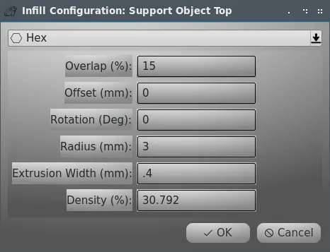
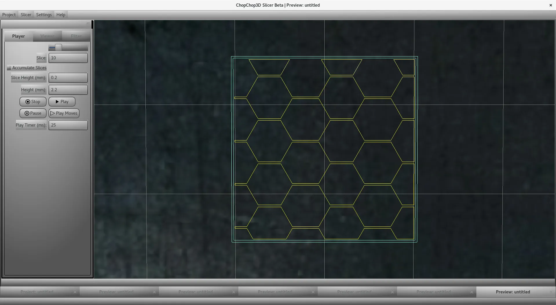
Hex
The hexagon infill is defined as follows:- Overlap: it is the amount of overlap of the infill with the shell.
- Offset: it is an offset that allows to shift the infill. For instance, it can be used to have a line to match a specific corner of a part.
- Rotation: it is the rotation in degrees of the line.
- Radius: the radius of the hexagon.
- Extrusion Width: it is the extrusion width used, that can be different from the nozzle diameter.
- Density: it is the density in percents of the infill, you can use either the Distance or the Density.
Strong Hex
It is a variant of the hexagon infill with a different pattern than the hex infill, generating a coarser structure with larger "lines".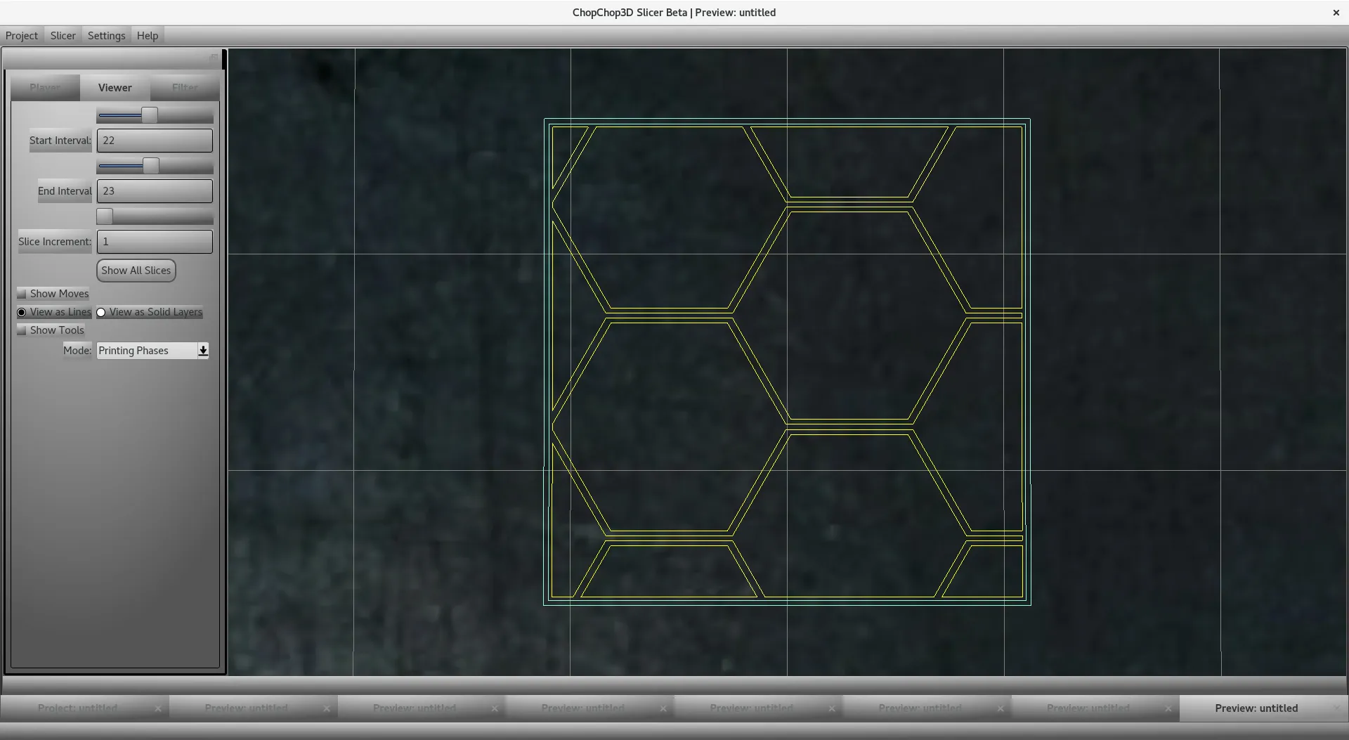
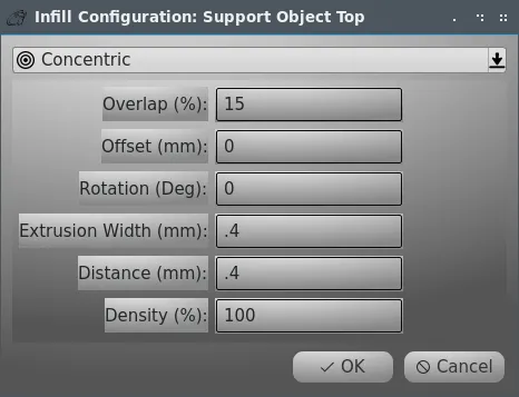
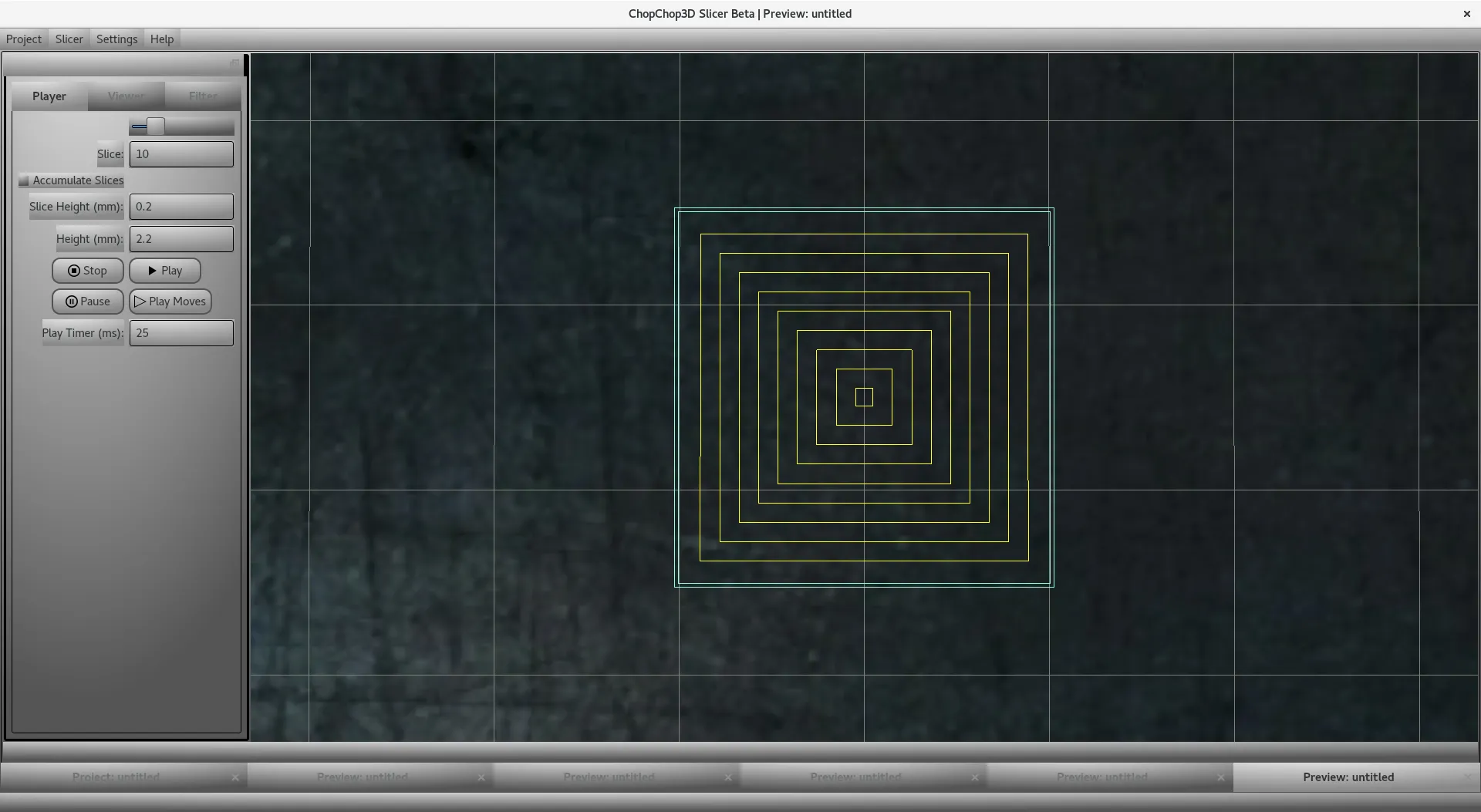
Concentric
The concentric pattern follows the shell pattern by progressive offsetting. Only the following settings are taken in account:- Overlap: it is the amount of overlap of the infill with the shell.
- Extrusion Width: it is the extrusion width used, that can be different from the nozzle diameter.
- Distance: it is the distance in between lines.
- Density: it is the density in percents of the infill, you can use either the Distance or the Density.
Round ZigZag
It is a variation of the ZigZag pattern where ends are joined by half circle instead of following the shell. It can be used for supports.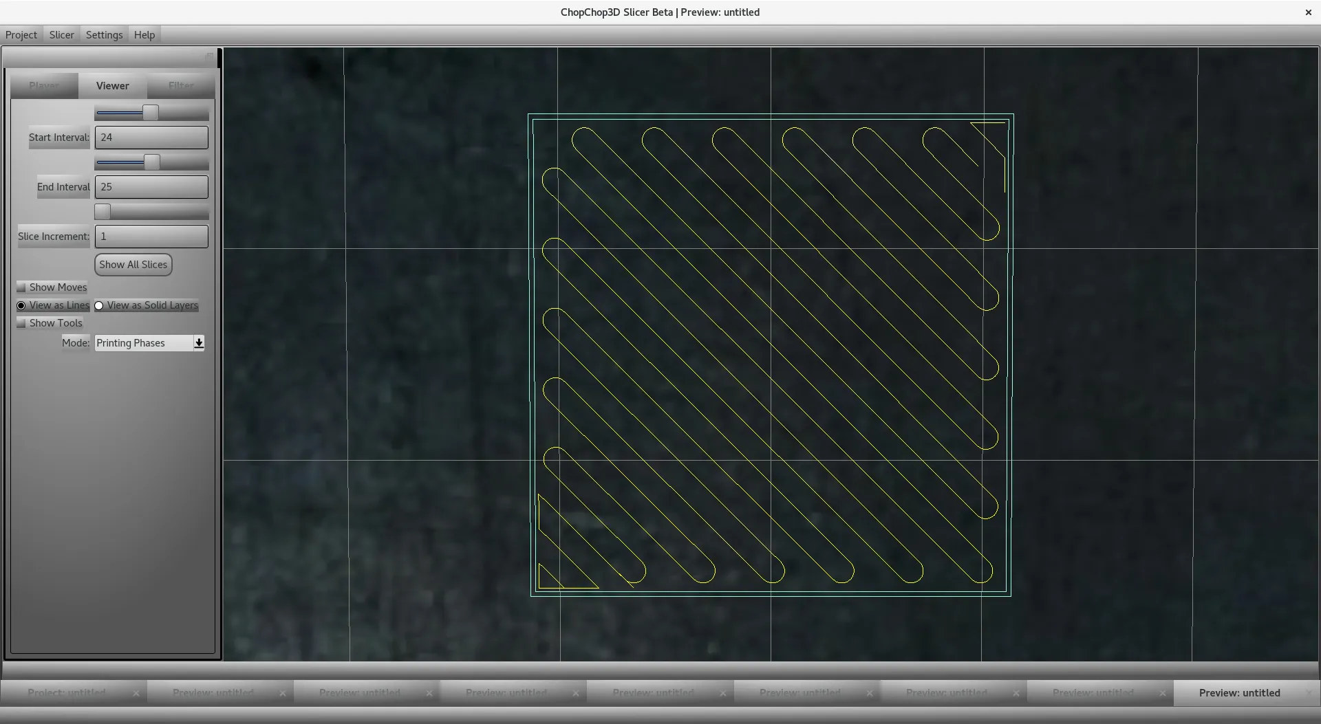
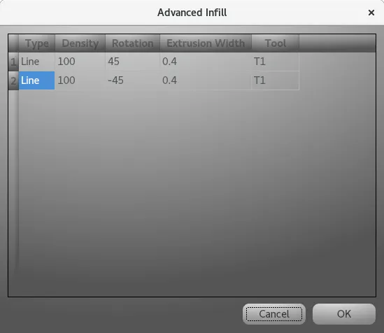
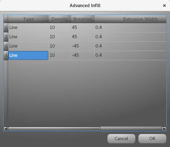
Advanced Infill
An Advanced Infill is an ordered list of Infill/Extruder definitions that are applied one after each other given the slice index. This feature can be applied in the context of the Top/Bottom or Infill print phases.
When you perform a right click you have access to the contextual menu.
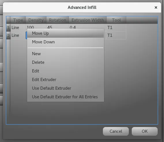
- Move Up and Move Down are used to set the order of the infills.
- New creates a new infill entry.
- Delete deletes a given infill entry.
- Edit opens the associated Infill dialog for edition.
- Edit Extruder opens the associated Extruder dialog for edition.
- Use Default Extruder applies the default extruder for the selected items.
- Use Default Extruder for all Entries applies the default extruder to all entries.
Example
- Example Template of a Quick Slice Top/Bottom Line infill, we just cross by 90 degrees. This is used for a Linear Infill as found in the Quick Slicer.
Shifted Infills
Typically for organic models such as a sculpture, you do not want to put a lot of infill but you want to have enough in order to build on it other printing phases. There is a limit on which it is difficult to go under. A low infill percentage means for instance on a Linear infill that the distance grows a lot, but we can take advantage of offset and/or rotation parameters to shift the infill a bit from layer to layer, enabling to cover more surface with less infill and helping the coverage for the top/bottom printing phases.
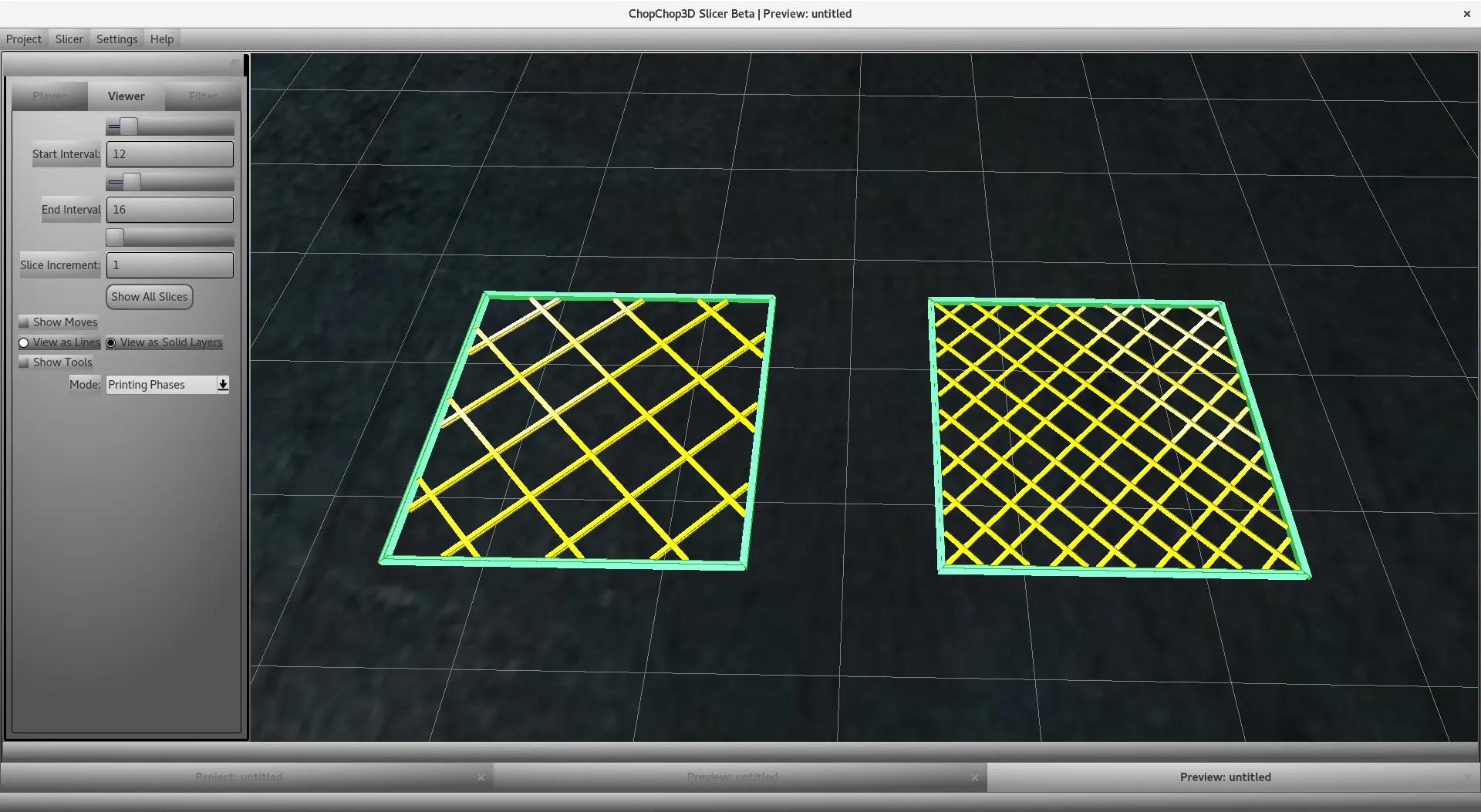
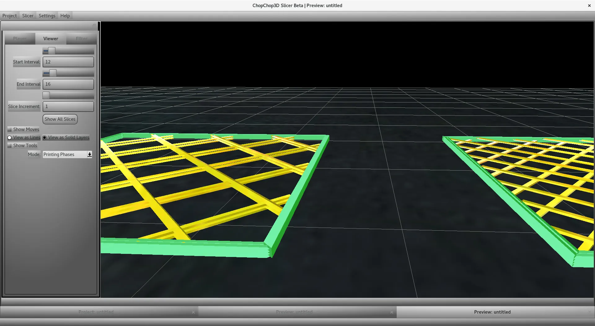
The next screenshot shows a 10% linear infill on the left, and the same 10% linear infill on the right with an additional offset to cover more surface. We call such technique a Shifted Infill .
This advanced infill is performed on 4 layers while the regular one is performed on 2.
The first entry has no offset, the second has an offset, the third entry has no offset and the last one has an offset.
You can see there is a repetition on the left for the pattern that repeats each 2 layers, while there is no repetition on the right pattern that repeats each 4 layers.
To ease the setup of such kind of infill, right click to show the contextual menu in the Advanced Infill dialog and select the Shifted Infill Generator
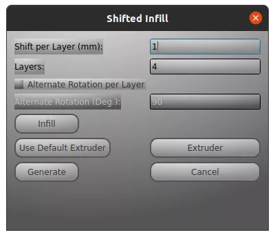
- First, set the shift per layer and the number of layers the shifted infill will span
- After, setup the infill by clicking on the Infill button, showing up the Infill dialog
- Then, set the extruder either using directly the Default Extruder button and/or by using the Extruder button that will popup the Extruder dialog with all associated parameters
- Finally, generate the infill that will be put inside the Advanced Infill dialog
Different shifted infill examples are provided in the printer Creality Ender3 in the bundle Shifted Infills
Bouligand Infill Generator
The Bouligand Infill Generator can be used to generate quickly a Bouligand inspired infill using the Linear Infill with various rotations. Please check Bouligand structure for further details . In order to access it perform a right-click in the Advanced Infill dialog to show the contextual menu and then click on the Bouligand Infill Generator.
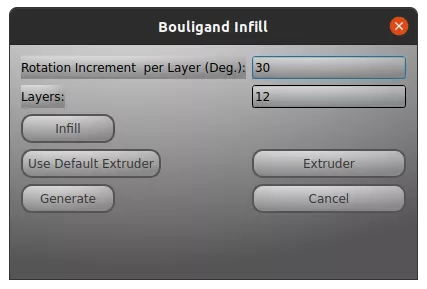
The workflow is very similar to the Shifted Infill generator.
- First, set the rotation per layer and the number of layers the infill will span
- After, setup the infill by clicking on the Infill button, showing up the Infill dialog
- Then, set the extruder either using directly the Default Extruder button and/or by using the Extruder button that will popup the Extruder dialog with all associated parameters
- Finally, generate the infill that will be put inside the Advanced Infill dialog
Tool Change
For each Infill there is a an Extruder/Tool definition attached to it. You can edit the GCode section of the Extruder to set the tool and the tool change required. If you are using the Quick Slicer, you will need to setup probably an Advanced Infill in case you need to customize Top/Bottom, Infill. For further details check out the Extruder document.