Content of this Document
The purpose of this document is to provide details on the supports system in the slicer:
- Introduction and overview of the supports system.
- Filtering and selection of support pillars in the browser.
- Setting up parameters at the slicer backend.
- Previewing and tuning parameters.

Introduction
Supports are mandatory in different 3D Printing Processes to enable printing complex geometries, loosely speaking we cannot print in the air and we need a support to print onto that will be removed after, during the post-processing of the part.
The supports system is decomposed in two parts in ChopChop3D Slicer:
- one part is found at the browser where you can perform a selection/filtering of support pillars;
- and another part is found at the slicer parameters where you can choose what kind of supports you want to create and to set associated infills and extruders for the creation of such supports.
Why such decomposition ? Because ChopChop3D Slicer enables to generate supports in different ways:
- manually or automatically generated supports pillars on the mesh,
- automatically generated supports from the slices,
- and an hybrid strategy using supports pillars on the mesh that acts as a filter on the generated supports on the slices.
Also, the automatically generated supports is not ideal because you cannot select/filter what pillars you want to keep or not. Its advantage is that it generates only parts that need supports according to the layer height, reducing filament usage and reducing print time.
But now, this is no more a limitation because you can use either one or the other directly, or combine both of them together.
Filtering and selection of support pillars
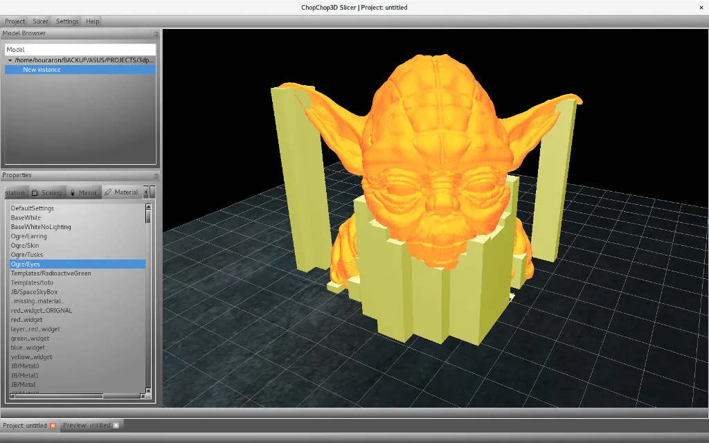
First, you need to create a new project, to import a mesh that probably need supports, then you double click on such mesh and perform a right click to obtain the menu, where you will click on the Supports.
We are using this STL model of Yoda for this document http://www.thingiverse.com/thing:14104 .
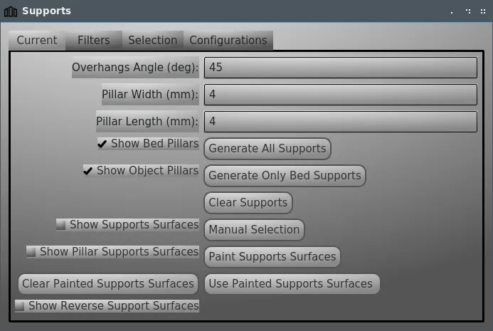
This will show the following dialog that contains few tabs:
- Current : that holds the current supports configuration with the overhangs angle, the size of pillars.
- Filters : that contains filters to filter out for instance too small area supports or too small in length.
- Selection : that can be used for difficult to pick support pillars.
- Configurations : that list all supports configurations attached to such mesh. Since manual selection of support pillars is very tedious and error prone, we allow to store several configurations for each mesh.
Current Tab
This tab holds the current configuration:
- The overhangs angle specified in degrees.
- The width and length of support pillars in millimeters. NB: Do not forget to check filters if you modify those.
- Show supports surfaces: which is very useful to visualize the facets that may need some pillar supports.
- Generate all supports: if you need to generate automatic supports for both bed and model.
- Generate only bed supports: if you need to generate only bed supports.
- Clear Supports: that disables all support pillars.
- Manual Selection: that enables to select/deselect support pillars.
- Paint Supports Surfaces: un/paint supports surfaces to perform selection of support pillars.
- Clear Painted Supports Surfaces: clear painted supports surfaces.
- Use Painted Supports Surfaces: use painted supports surfaces on the current selection of support pillars.
Show Supports Surfaces
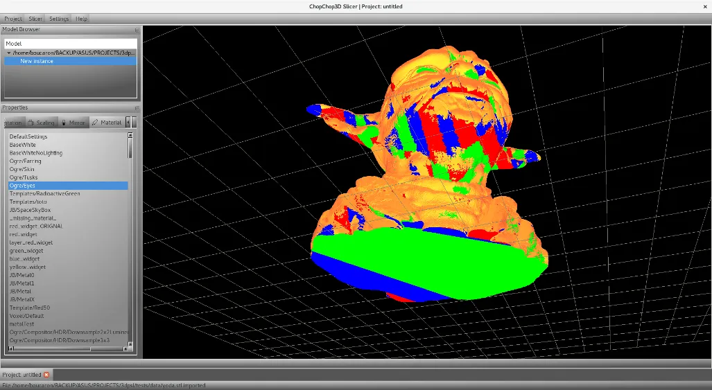
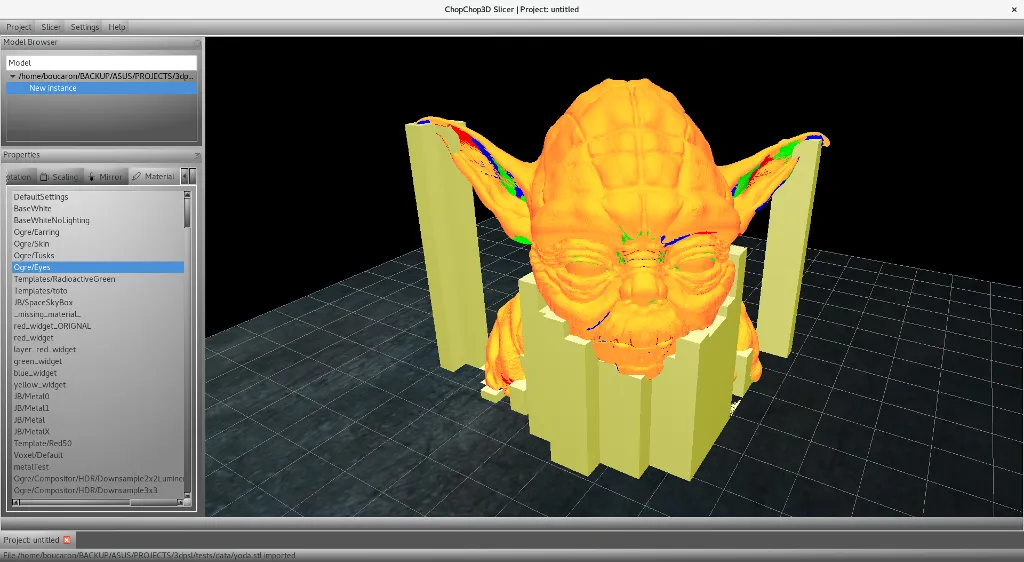
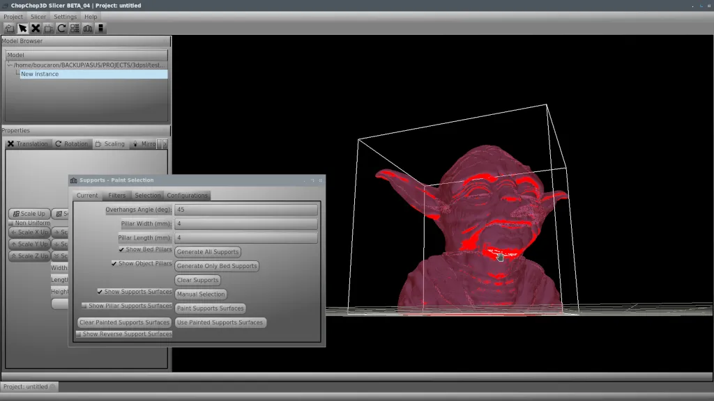
First, we want to see what are the surfaces needing supports pillars, we just click on Show Supports Surfaces, you are asked for confirmation, click on Yes and you will obtain a similar result. The colors red, green and blue denotes such surfaces needing supports, you can change the material of your mesh to ease visualization of such surfaces needing supports. Those colors are used to denote the grid of pillars.

Generate Only Bed Supports
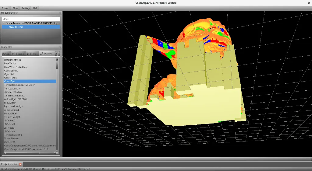
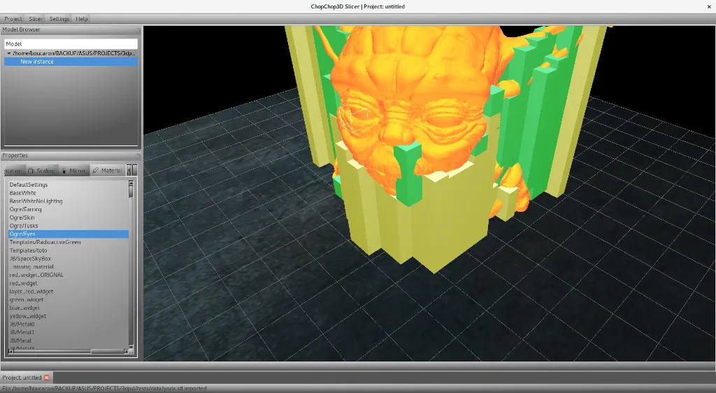
Now, we want to generate automatically only bed support pillars, we click on Generate Only Bed Supports and we obtain the following. Do not forget to check under your model, here for instance the model does not sit on the bed, so we have supports underneath.
Generate All Supports
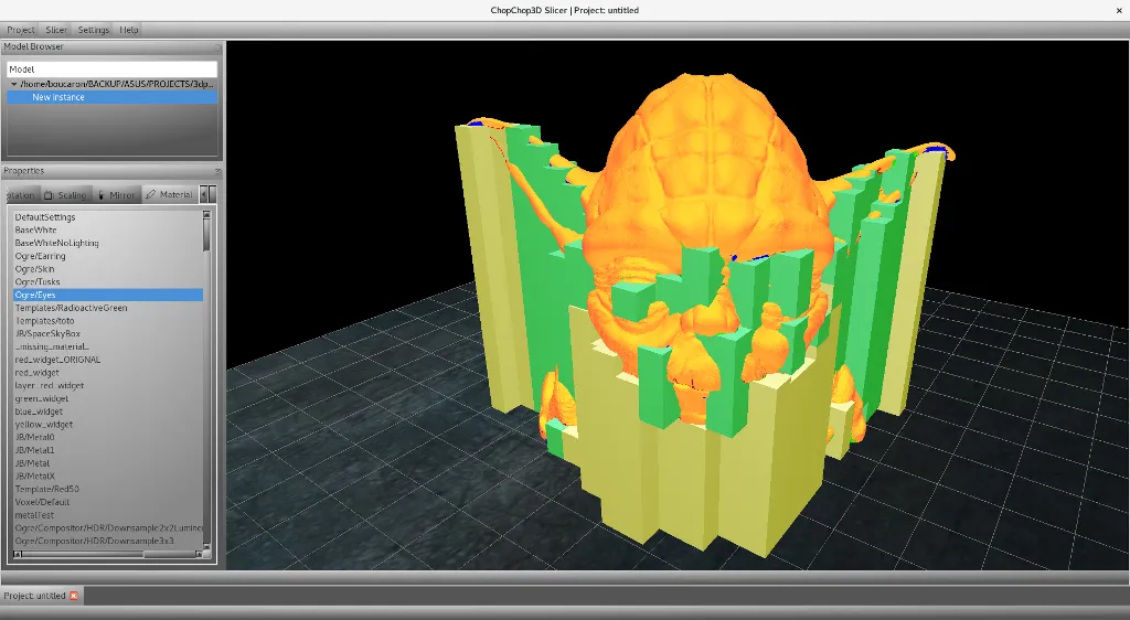
After having a look to the supports surface, we see that we may need some supports under the nose and in a ear, we just click on Generate All Supports to see the whole supports pillars picture (where we are asked for a confirmation, we select Yes). We obtain the following, which is not acceptable and will generate too many model supports that will ruin the surface of the model. Note that model support pillars are denoted with another colour.
Manual Selection
Now, we click on the Manual Selection, the title of the supports dialog is changed. When we move the cursor on the model if a pillar is selected, it is shown with a red transparent material, to remove supports we just perform a left click.
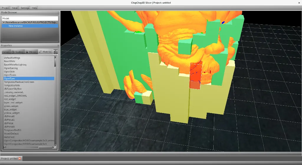
To add a support, simply move the cursor an empty pillar will be denoted as a box as follows just perform Alt + left click or Shift + left click

Clear Supports
Sometimes this is not ok, it is better to restart from scratch with no support pillars selected, click on Clear Supports, you will be asked for confirmation, click on Yes.
Paint Supports Surfaces
You can paint the supports surfaces to ask the generation of supports for the set of facets you painted. The Paint mode will be activated, you select facets with a left click and you erase with Alt + left click or Shift + left click (NB: the camera is locked, when the paint mode is active such that you can spray paint). Painted facets are shown in white.
Clear Painted Supports Surfaces
When clicked it clears all painted supports surfaces.
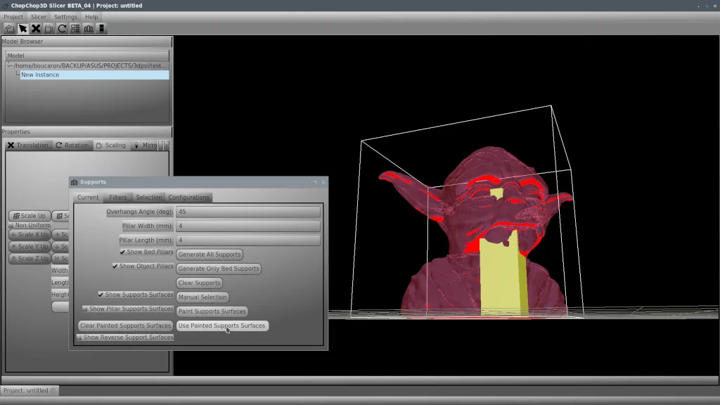
Use Painted Supports Surfaces
When clicked it add supports pillars associated to the selected facets. You do not need to cover all facets to enable a given pillar, at least one is needed to activate the supports.
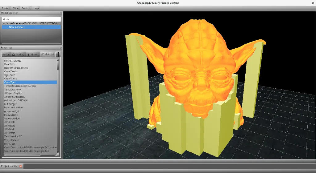
Overhangs Angle
The overhang angle is the maximum angle that your 3D Printer can print without needing support materials, it depends on various parameters for instance the material of the filament, the cooling fans configuration, the speed on XY axis to print. If your printer is capable to print steep overhangs angle you can reduce drastically the amount of material used.
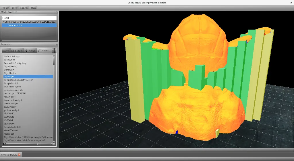
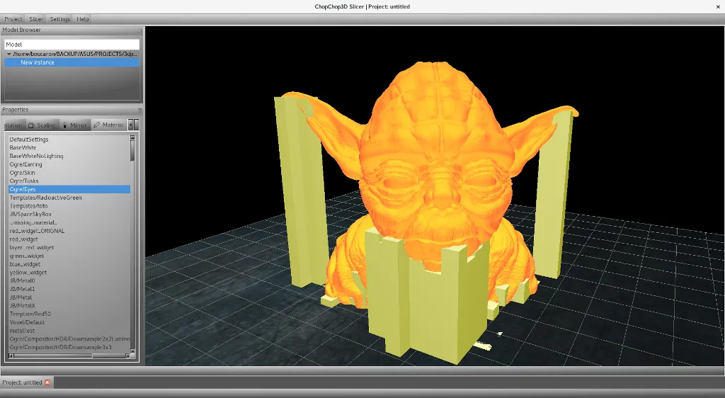
The first image is for 45 degrees while the second is for 35 degrees you can see an important reduction of support pillars under the chin of Yoda.
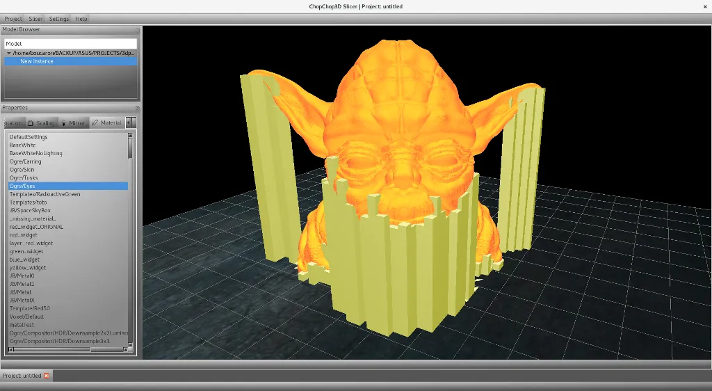
You can also refine the structure of the grid you just need to set the width and the length of pillars that can be asymmetric. NB: Do not forget to update filters accordingly. For instance the first screen shot is 2mm by 2mm and the next one a 1mm by 1mm.
Filters Tab
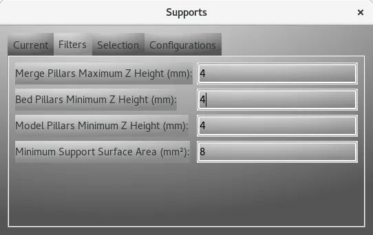
Now, we can have a look for various parameters found in the filter tab. One of them is used to allow to merged pillars in order to reduce the number of pillars inside the same location on the grid in X and Y. While other parameters are used to filter out too small in length pillars or too little area to support.
- Merge Pillars Maximum Z Height : enable to merge some pillars together according to a maximum length in millimeters.
- Bed Pillars Minimum Z Height : keep only bed pillars having such minimum length in millimeters.
- Model Pillars Minimum Z Height : similar to the previous one but for model pillars
- Minimum Support Surface Area : filter out pillars not having this total support surface (facet surface is approximated).
NB: Do not forget to update this parameter when changing the width and length of pillars in the Current Tab.
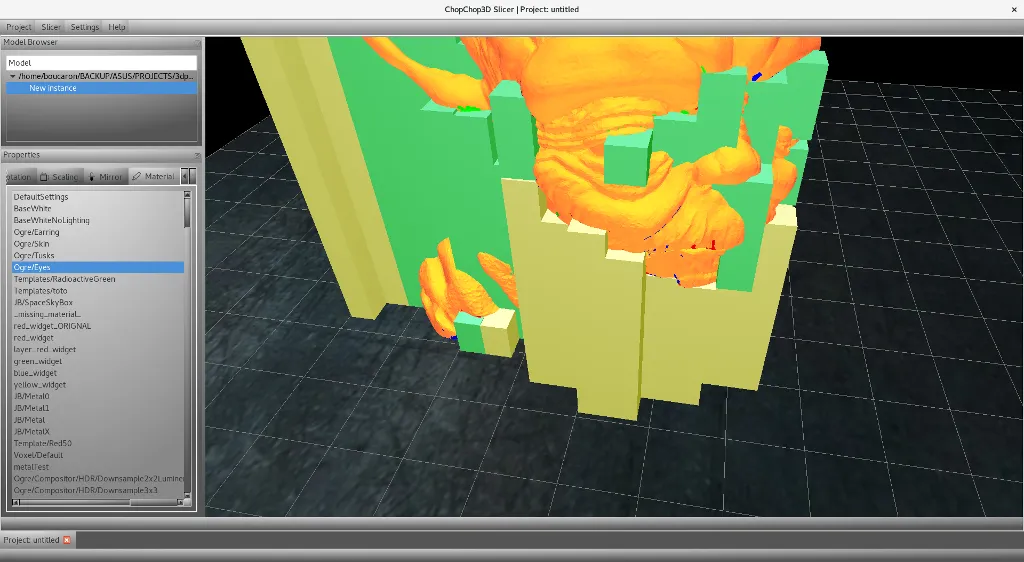
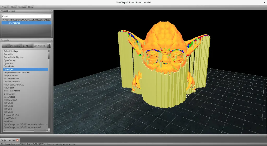
In the following image, we set the width and length of pillars to 1 mm for each and we set to 0 the minimum surface area. You can see that it leads to the generation of many small pillars at the base of the Yoda. Also, it look like many spurious pillars end up on the eyes and so on, this is caused by the successive merge of pillars.
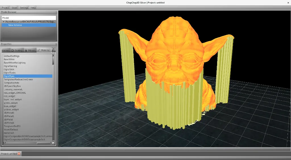
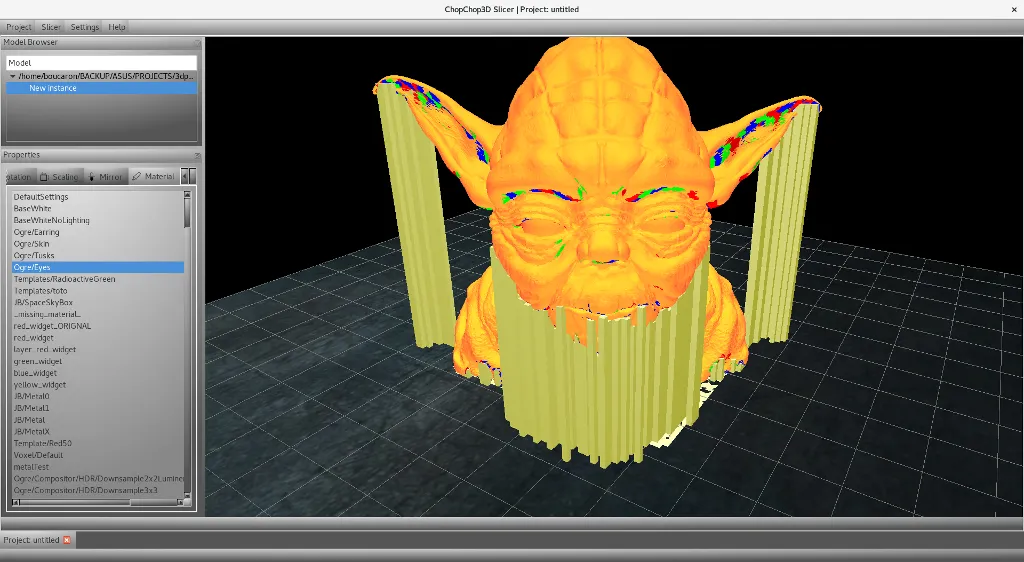
In the next image, we set the minimum surface area to be equal to 1. You can see that we removed many pillars that where just supporting very small facets.
Selection Tab
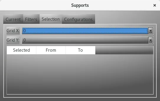
This tab is to help to select/deselect one or several pillars in the same cell on X,Y but not only. You can also select/deselect several pillars in the same cell, on the same column or on the same row of the grid, through a right click to show the contextual menu.
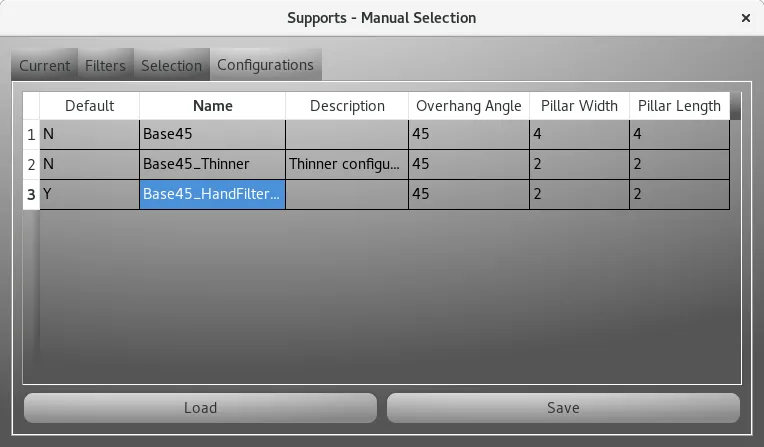
Configurations Tab
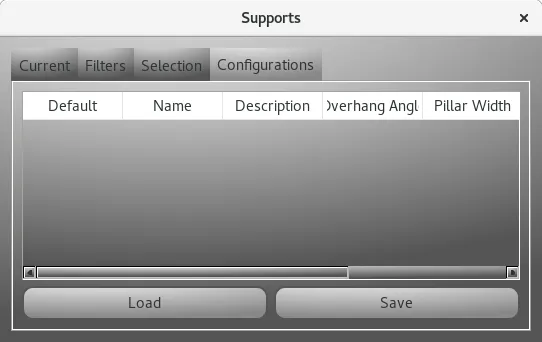
This tab is used to load/save and delete in memory pillars configurations. Since the manual selection of pillars is a tedious job and it changes from a material or a 3D Printer, we allow to store several configurations for each mesh.
Important : Those configurations will be stored in the database only when the project is stored in the database, do not forget this point otherwise you will loose such settings.
The next screenshot shows an example having a few configurations.
NB: the delete action is only reachable by a right click to show the contextual menu.
Setting up parameters at the slicer backend
A Support Tab is found in both Quick Slicer and Slicer dialogs. This tab is decomposed in a few tabs also:- General : contains main parameters.
- Bed Top : contains parameters of the top layers of Bed supports.
- Bed Bottom : contains parameters of the bottom layers of Bed supports.
- Bed Pillars : contains parameters that are not in the top and bottom layers of Bed supports.
- Object Top : similar to Bed Top but for Object supports.
- Object Bottom : similar to Object Bottom but for Object supports.
- Object Pillars : similar to Object Pillars but for Object supports.
- Advanced : contains specific parameters only for advanced users.

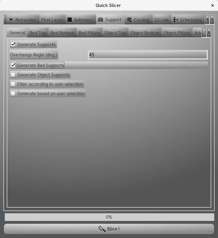
General
The General tab is where you enable the generation of supports, bed supports and object supports (called also model or mesh supports), where you choose to use the default pillar selection you made (detailed in the previous section) either as a filter on the automatic generated support surfaces by the slicer, or if you want to force the slicer to use your pillar selection as support surfaces.
For example, the following selection enables automatic generation of only bed supports using the provided overhangs angle of 45 degrees, but we do not take in account for any user selection for support pillars.
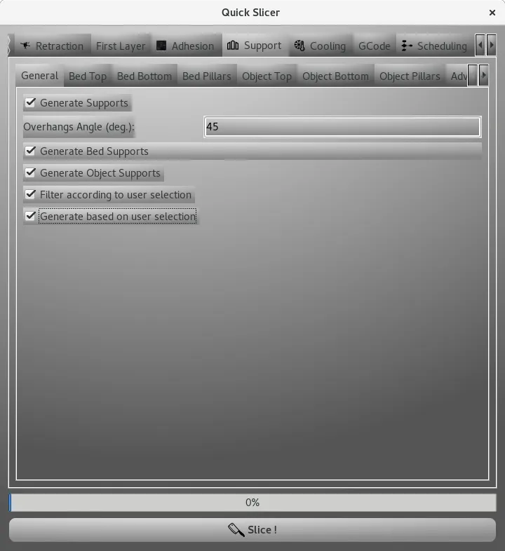
Next example, the following selection acts for automatic generation of bed and objects supports, but such supports are filtered using the default user support selection of each mesh.

Another example, where this time the default user support selection is used to generate support pillars.
Bed Top
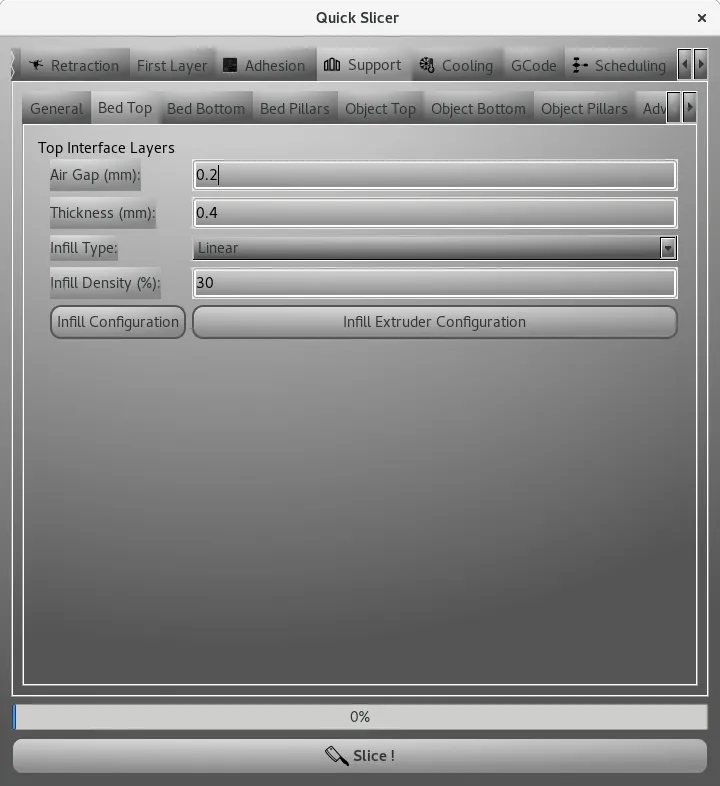
This defines the top interface layers of the Bed supports with:
- Air Gap : is the air gap in millimeters between the last layer of the bed top before reaching the surface to be supported.
- Thickness : is the thickness in millimeters of the top interface layers.
- Infill Type : the type of infill used for the top interface layers.
- Infill Density : the infill density in percentage for the top interface layers.
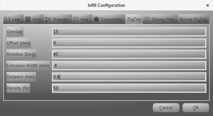
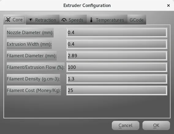
The infill is configured through the Infill Configuration button, also the Infill Extruder can be configured through the Infill Extruder Configuration button.
NB: it is possible to perform a tool change/extruder change at this stage.
Bed Bottom
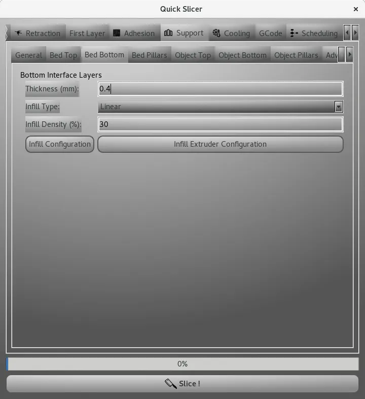
This defines the bottom interface layers of the Bed supports with :
- Thickness : is the thickness in millimeters of the bottom interface layers.
- Infill Type : the type of infill used for the bottom interface layers.
- Infill Density : the infill density in percentage for the bottom interface layers.
Similarly the infill pattern and all parameters of the used extruder can be set.
Bed Pillars
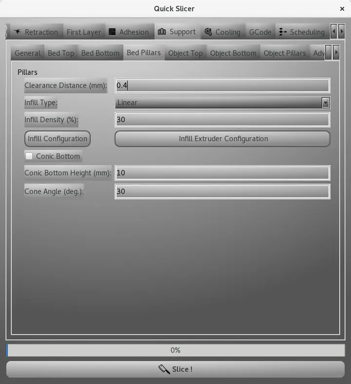
This defines the layers of the pillars that are not top or bottom interfaces:
- Clearance Distance : the clearance distance in millimeters from the model.
- Infill Type : the type of infill used for the bottom interface layers.
- Infill Density : the infill density in percentage for the bottom interface layers.
- Similarly the infill pattern and all parameters of the used extruder can be set.
- Conic Bottom : is a conic bottom will be used, this enables to have stronger supports and merge near/adjacent supports to create stronger island.
- Conic Bottom Height : the height from where the cone starts.
- Cone Angle : the angle in degrees of the angle of the cone.
Object Top
This is similar to Bed Top but applied only to Object supports.
Object Bottom
This is similar to Bed Bottom but applied only to Object supports.
NB: The main difference is that an Air Gap in millimeters can be specified in order to control how the Object support sticks to the model. It is possible to perform a tool change/extruder change at this stage.
Object Pillars
This is similar to Bed Pillars but applied only to Object supports.
Advanced
Not documented
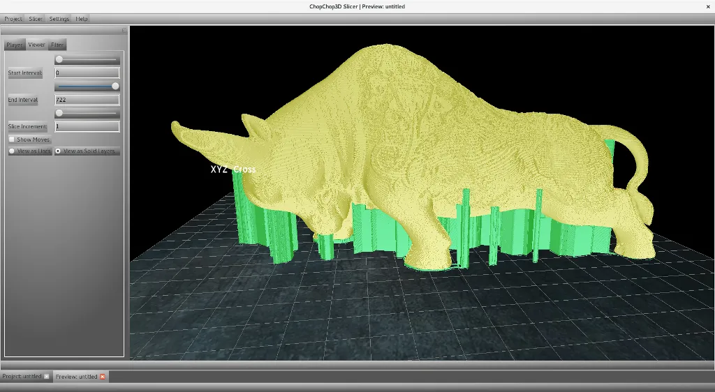
Previewing and tuning parameters
ChopChop3D allows to tinker with configurations and to show multiple previews, allowing to compare graphically what is going on, we are going to take advantage of this to show how this can be used to refine our parameters for supports.
Layer height and supports
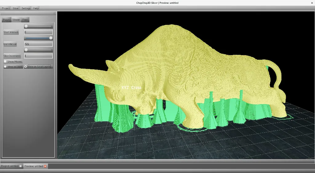
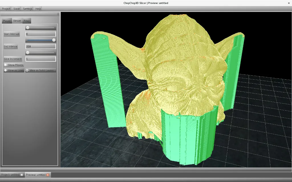
First, we said quickly that mesh generated supports are too pessimistic with respect to supports generated based on layers generated by the slicer. The following image is the mesh bed supports.
We quick slice at 0.2 with only bed supports at a 45 degrees overhangs and we obtain the following. It seems that there are a bit less supports.
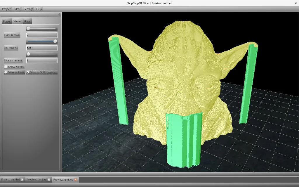
Then, we quick slice at 0.1 with the same 45 degrees overhangs and you can see that the obtained toolpath does not contain so many supports under the ears and the chin.
Conic Base
Lot of failures using supports happens due to lack of adhesion, we can help through an increase of the surface and also to join together very thin pillars. The following example shows such kind of issues.
After enabling the conic base in bed supports with a height of 10 mm and an angle of 10 degrees, we obtain the following, many supports are joined together providing a strong foundation.