Content of this Document
This document provides a detailed description of the Quick Slicer and associated parameters.
If you want to have a more in depth of slicing parameters, you are at the right place.
Introduction
The Quick Slicer is a simplified view of the ChopChop3D Slicer: it is not simpler. It still covers a large subset of the Slicer features.
The simplification is performed at those levels:
- There is only a layer range with a given layer height as found in many slicers.
- A Default Extruder is shared by all printing phases, except for the Supports that can be customized if required. (If you want to know more about Extruders in the Slicer you can check this document.)
- You have a simplified set of parameters for the First Layer
Quick Slicer overview
Requirement You need to have at least one STL model inside an existing or new Project.
Go in the Main menu and click on "Slicer/Quick Slice".
The quick slice panel is decomposed as follow:
- Profile: this is used to load/unload Quick slice profiles.
- Models: this is used to set configurations to models.
- Core: that contains fundamental parameters such as height of layers, shell thickness, extrusion flow, filament diameter, extruder nozzle size.
- Temperatures: for the bed, the extruder and the fan speed.
- Speeds: that contains all speeds related to move, to print, to extrusion.
- Retraction: that contains all parameters related to retraction settings.
- Adhesion: that contains specific parameters for Skirt, Raft and Brim settings to improve adhesion of parts to the bed.
- Support: that contains all settings to handle Support structures.
- Cooling: that contains all settings for the Cooling.
- GCode: that contains settings related to the printer for the GCode generation.
- First layer: that contains specific settings when printing the first layer.
- Scheduling: that contains settings related to the order of each kind of toolpath performed for each slice.
- Travel: that contains settings related to travel computation of each kind of toolpath.
Profile
This is the entry tab that allows to select the Printer, the Bundle and the Profile to be used for Quick Slice.
Important: there is not any kind of auto-saving of the modified profile, if you performed any modification on a profile, you will have to save it explicitly.
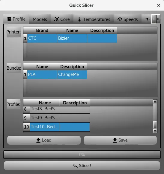
- Load Just select the Printer, the Bundle and the Profile, then click on Load button. You will be asked for confirmation.
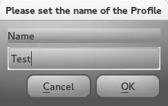
- Save Similarly to Load, select the Printer, the Bundle, then click on Save button. You will be asked the name of the profile to save.
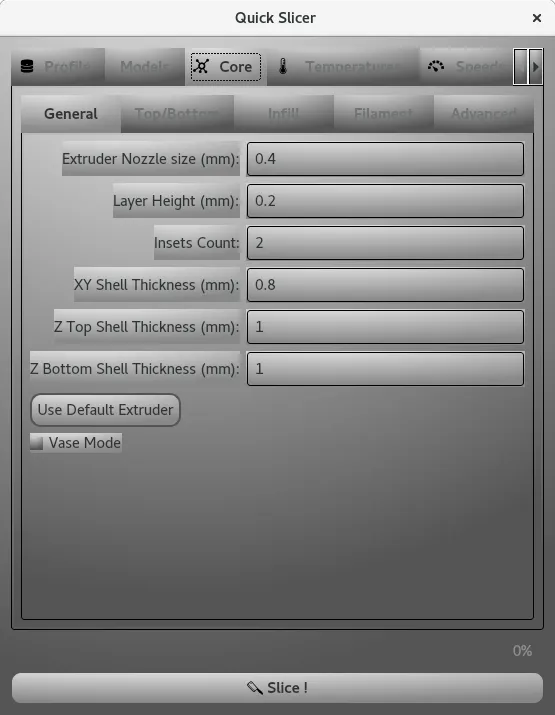
- General contains general parameters of the slicing.
- Insets contains all parameters for the Insets.
- Top/Bottom contains all parameters for the Top and Bottom Infills.
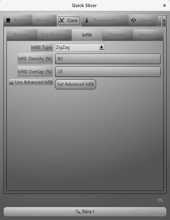
- Infill contains all parameters for the Infill.
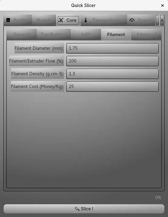
- Filament contains all parameters for the Filament.
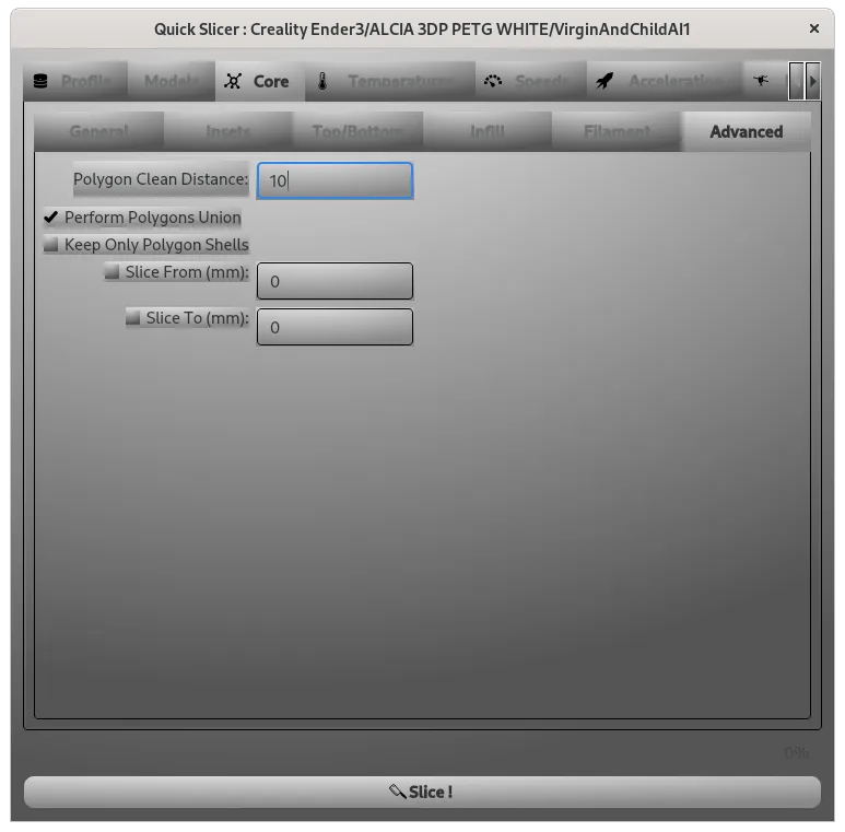
- Advanced contains more Advanced parameters affecting print quality and other features.
- Extruder Nozzle Size This is the extruder nozzle side in millimeter. It will be the extrusion width used for nearly all the printing phases except Supports that are customizable.
-
Layer Height: The layer increment is the main parameter that sets the quality of your print.
It should be in general strictly less or equal to 80% of the nozzle diameter of your extruder (for strong parts it should be less or equal to 50%). - Insets Count/XY Shell Thickness: Both parameters represent the same value, one is specified in millimeters and the other one in the number of insets performed.
Those parameters sets the thickness of the shell, it affects the rigidity of the part and also the time spent to print the model. - Z Top Shell Thickness: This parameter sets the thickness of the top of the shell, it affects the strength of the part and also the time spent to print the model.
- Z Bottom Shell Thickness : This parameter sets the thickness of the bottom of the shell, it affects the strength of the part and also the time spent to print the model.
- Use Default Extruder This button propagates the Default Extruder you set to all printing phases of the current profile.
- Vase Mode This checkbox activates the Vase Mode.
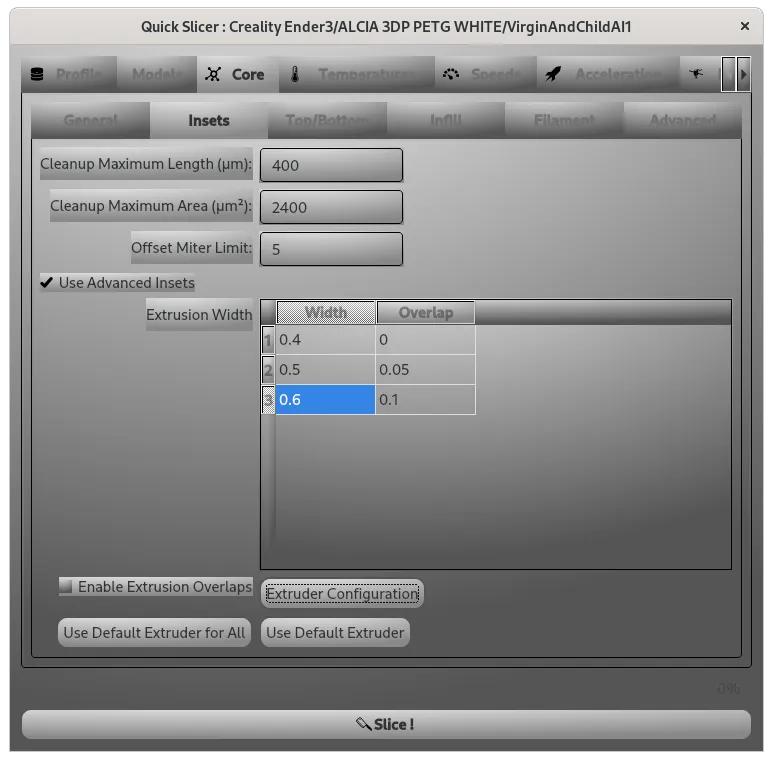
- Cleanup Maximum Length is removing all insets having a perimeter smaller than the given length. It is used to filter out non printable insets.
- Cleanup Maximum Area is removing all insets having an area smaller than the given area. It is used to filter out non printable insets.
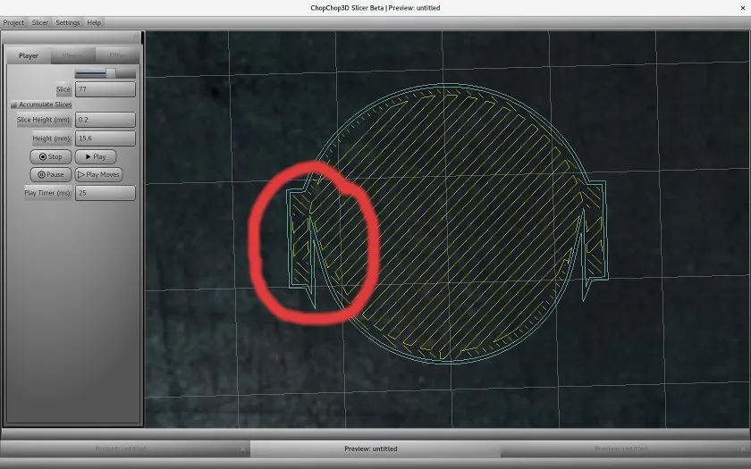
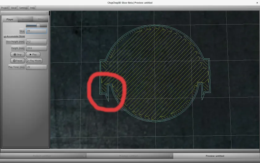
- Offset Miter Limit is setting the ratio of the point length to the extrusion width before the mitered join becomes a beveled square joint. The value of 10 is giving sharp details.
Small example, the miter limit is set to 10.
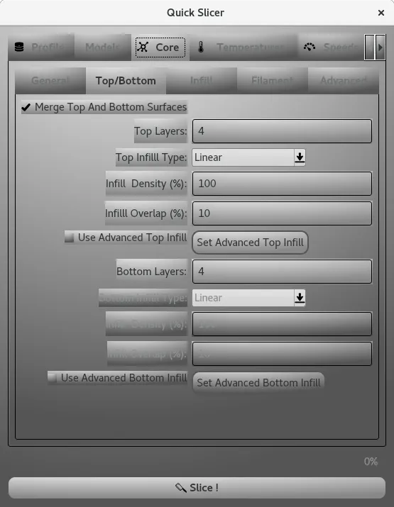
- Merge Top and Bottom Surfaces is a flag merging together Top/Bottom surfaces inside the same printing phase (same extruder, same infill), when enabled the parameters of the Top are used for the Bottom printing phase too.
- Top Layers it is the number of top layers.
- Top Infill Type it is the infill applied if Use Advanced Top Infill is disabled
- Infill Density it is the percentage of the previous infill
- Infill Overlap it is the amount of overlap with the Insets
- Use Advanced Top Infill when enabled, the advanced top infill is used
- Set Advanced Top Infill opens the Advanced Infill dialog associated to the Top print phase. You can have further details in the Infill document.
- The same naming pattern applies to all Bottom parameters, they are applied to the Bottom printing phase.
- Infill Type it is the infill applied if Use Advanced Infill is disabled
- Infill Density it is the percentage of the previous infill
- Infill Overlap it is the amount of overlap with the Insets
- Use Advanced Infill when enabled, the advanced top infill is used
- Set Advanced Infill opens the Advanced Infill dialog associated to the Infill print phase. You can have further details in the Infill document.
- Filament Diameter: This is an important parameter for the quality of the model, please ensure that this value is correct.
- Filament/Extruder Flow: This parameter allows to fine tune the extrusion flow of the extruder according to the filament used.
- Filament Density: This parameter sets the density of the filament that is used to compute the weight.
- Filament Cost: This parameter set the price per Kg of the filament to compute the cost.
- Polygon Clean Distance: is reducing the size of polygons by applying the given distance in µm. Most probably your printer is not able to print details under 10µm, it helps to reduce the size of the polygons, speed up the slicing and reduce the size of the GCode. If you are using a high precision printer using SLA for instance, you can set this value to 0. The value of 5 is a good balance.
- Perform Polygons Unions is performing the union of overlapping polygons that can be found during the Vectorization. It should be enabled by default.
- Keep Only Polygon Shells is keeping the parent polygon inside a hierarchy of polygons. For instance, it can be used to print in Vase mode a Vase that was not design as a full solid model, or if you have an hollowed model that you want to print in solid mode.
- Slice From and Slice To allows to slice a range. It can be used for instance to segment the print of a model too big to fit your printer, or to recover a failed print due to power loss.
- Use Advanced Insets enables to create a list of insets and set for each inset specific extruder parameters, including overlap between each inset.
- Print speed for all print moves.
- It also possible to set a specific print speed for:
- Insets for the first and last one, interpolation on the speed if performed. If you print from inside to outside, the last inset will be the visible surface, you can print it slower to improve the print quality.
- Infills.
- Top.
- Bottom.
- It also possible to set a specific print speed for:
- Move speed on XY and on Z.
- Retraction speed. The optional retraction restart speed, in case you want a different speed when restarting/repriming the nozzle.
- Avoid Crossing Perimeters Speed, if you selected the option at the Travel tab
- If the retraction is enabled or not.
- The distance in millimeters to retract the filament.
- The restart distance that is the amount of filament to extrude before reextracting again.
You can start with the same value as found for the distance and tune it progressively. - Lift Z if you want to lift the Z axis while performing the retraction.
- The minimum travel distance to be performed before re-enabling the retraction.
- The minimum extrusion distance to be performed before re-enabling the retraction.
Printer, Bundle
You can create and you can remove entries for both Printers and Bundles through the Contextual Menu that can be accessed through a Right Click in the Printer or Bundle List.
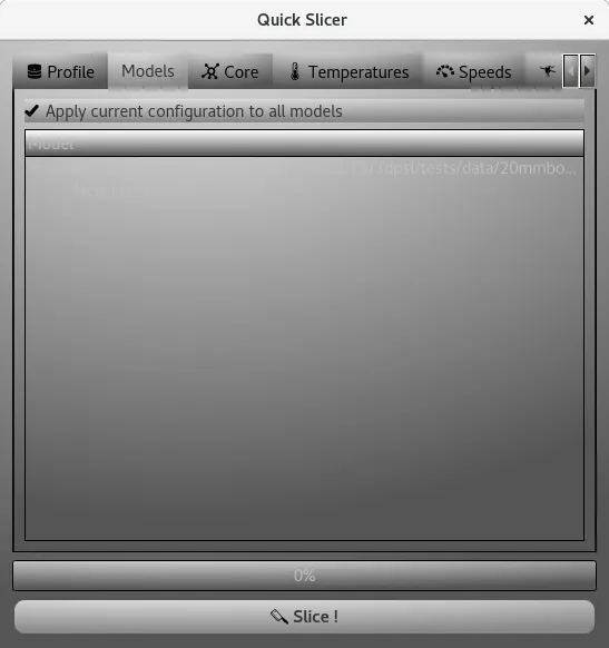
Models
Use this tab to set the same configuration to all models, or if you want to set to each model a specific configuration
Core
This is the main tab used to set core parameters of the slicer. It is decomposed as follows :
While here, the miter limit is set to 5.
Temperatures
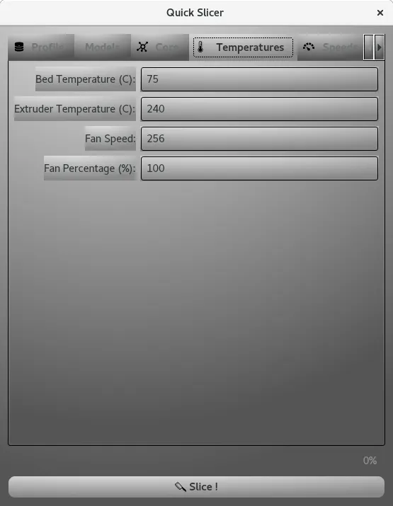
Temperature of the extruder is critical, it depends mostly on the material, please refer to the information given by the manufacturer.
The temperature of the bed is important also to ensure a good adhesion of the part.
The fan speed is critical to ensure enough cooling of the part, you can use either the native value or the percentage.
Speeds
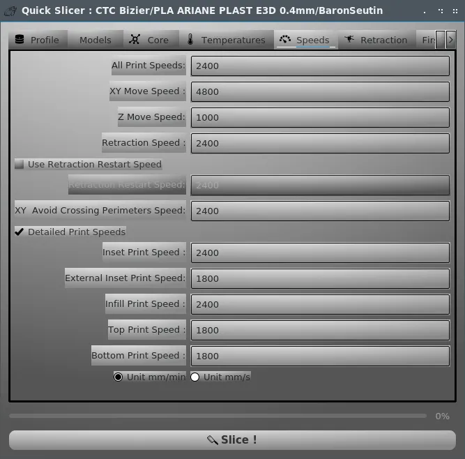
You can set the speeds for different kinds of moves:
Retraction
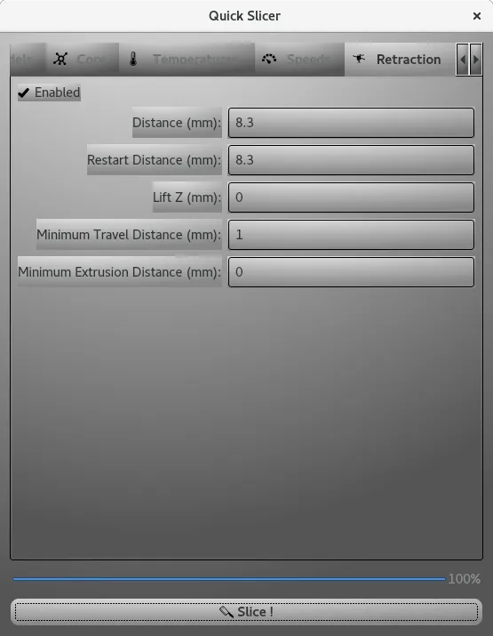
This tab is used to set various parameters for the retraction:
First layer
This tab is used to ensure a good first layer.
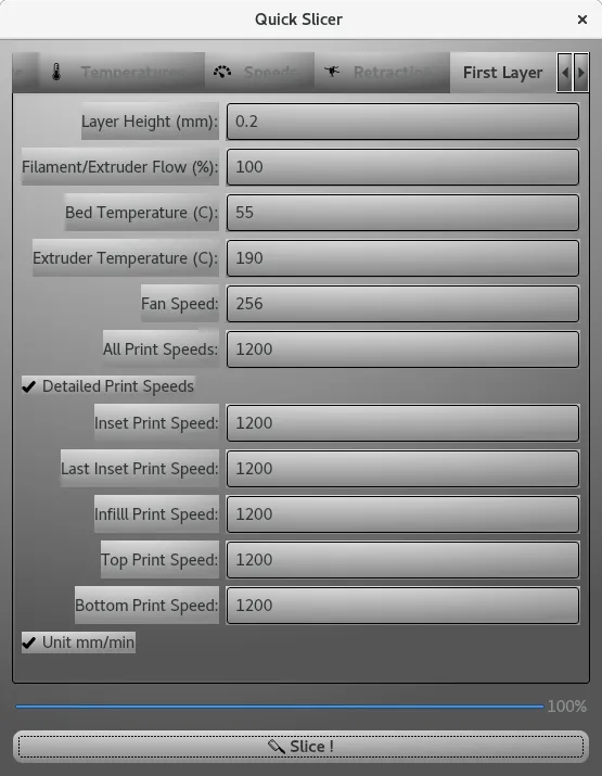
You can change the first layer height, several parameters regarding the extruder and print speeds that are critical.